CC-2401K2A-CS Copeland Communications Inc, CC-2401K2A-CS Datasheet - Page 14
CC-2401K2A-CS
Manufacturer Part Number
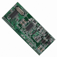
CC-2401K2A-CS
Description
MODEM 2400BAUD SECURE 3.3V
Manufacturer
Copeland Communications Inc
Datasheet
1.CC-2401K2A-CS.pdf
(66 pages)
Specifications of CC-2401K2A-CS
Data Format
V.21, V.22, V.23, Bell 103
Baud Rates
2.4k
Interface
UART
Voltage - Supply
3 V ~ 3.6 V
Mounting Type
Surface Mount
Package / Case
Module
For Use With
539-1002 - KIT EVALUATION WORLD MODEM II
Lead Free Status / RoHS Status
Contains lead / RoHS non-compliant
Other names
539-1010
CC-2401K2A-CS
CC-2401K2A-CS


© 2007, Copeland Communications, Inc.
V.42 HDLC Operation
The CC-2401 supports V.42 through hardware HDLC framing in all modem data modes. Frame packing and
unpacking including opening and closing flag generation and detection, CRC computation and checking, zero
insertion and deletion, and modem data transmission and reception are all performed by the CC-2401. V.42
error correction and V.42bis data compression must be performed by the host.
The digital link interface in this mode uses the same UART interface (8-bit data mode and 9-bit data formats)
as in the asynchronous modes, and the ninth data bit may be used as an escape by setting S15[0](NBE) = 1.
When using HDLC in 9-bit data mode, if the ninth bit is not used as an escape, it is ignored.
To use the HDLC feature on the CC-2401, the host must enable HDLC operation by setting S13[1](HDEN) = 1.
The host may initiate the call or answer the call using either the “ATDT#”, the “ATA” command or the auto
answer mode. Auto answer mode is implemented by setting register S00 (NR) to a non-zero value. When the
call is connected, a “c”, “d” or a “v” result is echoed to the host controller. The host may now send and receive
data across the UART using either the 8 or 9 bit data formats with flow control.
Once in this state, the CC-2401 begins framing data into the HDLC format. On the transmit side, if no data is
available from the host, the HDLC flag pattern is sent repeatedly. When data is available, the CC-2401
computes the CRC code throughout the frame, and the data is sent with the HDLC zero-bit insertion algorithm.
HDLC flow control operates in a similar manner to normal asynchronous flow control across the UART. To
operate flow control using the CTS pin to indicate when the CC-2401 is ready to accept a character, a DTE
rate higher than the line rate should be selected. The method of transmitting HDLC frames is as follows:
1.
The host then sends the ATRO command to the CC-2401 to initiate a V.23 turnaround and return to online
data mode.
The CC-2401 then changes its carrier frequency from 390 Hz to 1300 Hz) and wait to detect a 390 Hz
carrier for 440 ms. If the modem detects more than 40 ms of a 390 Hz carrier in a time window of 440 ms,
it echoes the “c” response. If the modem does not detect more than 40 ms of a 390 Hz carrier in a time
window of 440 ms, it hangs up and echoes the “N” (no carrier) character as a response.
Modem in Slave Mode
Enable Slave mode by configuring GPIO4 and INT# (SE2[7:6][GPIO4] = 11). The CC-2401 performs a
reverse turnaround when it detects a carrier drop longer than 20 ms. The CC-2401 then reverses and
waits to detect a 1300 Hz carrier for 400 ms. If the CC-2401 detects more than 40 ms of a 1300 Hz
carrier in a time window of 400 ms, it sets the S09[7] bit and the next character echoed by the CC-2401 is
a “v”.
If the CC-2401 doe not detect more than 40 ms of the 1300 Hz carrier in a time window of 400 ms, it
reverses again and waits to detect a 390 Hz carrier for 440 ms. Then if the CC-2401 detects more than
40 ms of a 390 Hz carrier in a time window of 220 ms, it sets the S09[7] bit, and the CC-2401 echoes a
“c”.
At this point, if the CC-2401 does not detect more than 40 ms of the 390 Hz carrier in a time window of
440 ms, it hangs up, sets the S09[7] bit, and the CC-2401 echoes a “N” (no carrier).
Successful completion of a turnaround procedure in master or slave mode automatically updates
S07[4](V23T) and S07[5] (V23R) to indicate the new status of the V.23 connection.
To avoid using the INT# pin, the host may also be notified of the INT# condition using the 9-bit data mode.
Setting S15[0] (NBE) = 1 and S0C[3] (9BF) = 0
function exactly as the INT# pin has been described.
After the call is connected, the host should begin sending the frame data to the CC-2401 using the CTS#
flow control to ensure data synchronicity.
Page 14 of 66
Data Sheet
b
configures the ninth bit on the CC-2401 TXD path to
CC-2401K2 Datasheet Rev 1.5
CC-2401K2
Related parts for CC-2401K2A-CS
Image
Part Number
Description
Manufacturer
Datasheet
Request
R

Part Number:
Description:
170 FOOT 24 CONDUCTOR, ST/ST, 100 MICRON, NUMBERED WITH PULLING EYE, INDIVIDUAL FIBERS ARE BUNDLED TOGETHER
Manufacturer:
DIGITHEAD
Part Number:
Description:
Relay; SSR; Cur-Rtg 25 A; Ctrl-V 4-32 VDC; Vol-Rtg 24-280 VAC; Panel; Key Locking Conn
Manufacturer:
Crydom Company
Datasheet:
Part Number:
Description:
Relay; SSR; Cur-Rtg 25 A; Ctrl-V 4-32 VDC; Vol-Rtg 24-280 VAC; Panel; Four Pin Screw
Manufacturer:
Crydom Company
Datasheet:
Part Number:
Description:
Relay; SSR; Cur-Rtg 50 A; Ctrl-V 4-32 VDC; Vol-Rtg 24-280 VAC; Panel; Four Pin Spring
Manufacturer:
Crydom Company
Datasheet:

Part Number:
Description:
CONV DC/DC 3W SNG 24V 3.3V PCB
Manufacturer:
TDK Corporation
Datasheet:
Part Number:
Description:
CONV DC/DC 6W SNGL 24V 12V PCB
Manufacturer:
TDK Corporation
Datasheet:
Part Number:
Description:
CONV DC/DC 6W SNGL 24V 5V PCB
Manufacturer:
TDK Corporation
Datasheet:
Part Number:
Description:
CONV DC/DC 6W SNGL 24V 3.3V PCB
Manufacturer:
TDK Corporation
Datasheet:
Part Number:
Description:
CONV DC/DC 10W SNGL 24V 5V PCB
Manufacturer:
TDK Corporation
Datasheet:

Part Number:
Description:
MODEM 2400BAUD SECURE 5V
Manufacturer:
Copeland Communications Inc
Datasheet:
Part Number:
Description:
MODEM 2400BAUD SERIAL 5V
Manufacturer:
Copeland Communications Inc
Datasheet:
Part Number:
Description:
MODEM 56KBAUD SERIAL V.92 5V
Manufacturer:
Copeland Communications Inc
Datasheet:

Part Number:
Description:
MODEM 2400 BAUD SERIAL
Manufacturer:
Copeland Communications Inc

Part Number:
Description:
MODEM 56K V.92 SERIAL
Manufacturer:
Copeland Communications Inc