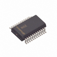
MAX7326AEG+ Maxim Integrated Products, MAX7326AEG+ Datasheet - Page 12

MAX7326AEG+
Manufacturer Part Number
MAX7326AEG+
Description
IC I/O EXPANDER I2C 16B 24QSOP
Manufacturer
Maxim Integrated Products
Datasheet
1.MAX7326ATG.pdf
(20 pages)
Specifications of MAX7326AEG+
Interface
I²C
Number Of I /o
16
Interrupt Output
Yes
Frequency - Clock
400kHz
Voltage - Supply
1.71 V ~ 5.5 V
Operating Temperature
-40°C ~ 125°C
Mounting Type
Surface Mount
Package / Case
24-QSOP
Includes
POR
Lead Free Status / RoHS Status
Lead free / RoHS Compliant
I
and 4 Inputs
If a port input data change occurs during the read
sequence, then INT is reasserted during the I
bit. The MAX7326 does not generate another interrupt
during a single-byte or multibyte read.
Input port data is sampled during the preceding I
acknowledge bit (the acknowledge bit for the I
address in the case of a single-byte or 2-byte read).
A multibyte read (more than 2 bytes before the I
STOP bit) from the group B ports of the MAX7326
repeatedly returns the status of the eight output ports,
read back as inputs.
A single-byte write to the group A ports of the
MAX7326 sets the logic state of the four I/O ports and
the 4-bit interrupt mask register and clears both the
internal transition flags and INT output when the master
acknowledges the slave address byte.
A single-byte write to the output ports of the MAX7326
sets the logic state of all eight ports.
A multibyte write to the group A ports of the MAX7326
repeatedly sets the logic state of the four I/O ports and
interrupt mask register.
A multibyte write to the group B ports of the MAX7326
repeatedly sets the logic state of all eight ports.
Figure 6. Reading Group A Ports of the MAX7326 (1 Data Byte)
12
2
C Port Expander with 12 Push-Pull Outputs
______________________________________________________________________________________
t
IV
PORTS
INT OUTPUT
SCL
S
MAX7326 SLAVE ADDRESS
2
2
C STOP
C slave
ACKNOWLEDGE
FROM MAX7326
R/W
2
2
C
C
1
A
A read from the group A ports of the MAX7326 starts
with the master transmitting the port group’s slave
address with the R/W bit set to high. The MAX7326
acknowledges the slave address and samples the
ports (takes a snapshot) during the acknowledge bit.
INT goes high (high impedance if an external pullup
resistor is not fitted) during the slave address acknowl-
edge. The master can then issue a STOP condition
after the acknowledge
taken, and the INT status remains unchanged if the
master terminates the serial transaction with no
acknowledge.
Typically, the master reads 1 or 2 bytes from the
MAX7326 with each byte being acknowledged by the
master upon reception.
The master can read one byte from the group A ports of
the MAX7326 and issues a STOP condition
this case, the MAX7326 transmits the current port data,
clears the transition flags, and resets the transition
detection. INT goes high (high impedance if an external
pullup resistor is not fitted) during the slave address
acknowledge. The new snapshot data is the current
port data transmitted to the master, and therefore, port
changes occuring during the transmission are detected.
INT remains high until the STOP condition.
t
t
IR
PH
PORT SNAPSHOT
O7
D7
O6
INT REMAINS HIGH UNTIL STOP CONDITION
D6
S = START CONDITION
P = STOP CONDITION
A = ACKNOWLEDGE FROM MASTER
I5
D5
I4
D4
I3
D3
(Figure
I2
PORT SNAPSHOT
D2
Reading from the MAX7326
O1
D1
6). The snapshot is not
O0
D0
t
PS
ACKNOWLEDGE
FROM MASTER
A
P
(Figure
t
IP
6). In


