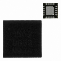
SX1502I087TRT Semtech, SX1502I087TRT Datasheet - Page 15

SX1502I087TRT
Manufacturer Part Number
SX1502I087TRT
Description
IC GPIO EXPANDER I2C 8CH 20QFN
Manufacturer
Semtech
Datasheet
1.SX1501I087TRT.pdf
(34 pages)
Specifications of SX1502I087TRT
Interface
I²C
Number Of I /o
8
Interrupt Output
Yes
Frequency - Clock
400kHz
Voltage - Supply
1.2 V ~ 5.5 V
Operating Temperature
-40°C ~ 85°C
Mounting Type
Surface Mount
Package / Case
20-QFN
Lead Free Status / RoHS Status
Lead free / RoHS Compliant
Other names
SX1502I087TR
Available stocks
Company
Part Number
Manufacturer
Quantity
Price
Company:
Part Number:
SX1502I087TRT
Manufacturer:
LTC
Quantity:
196
Part Number:
SX1502I087TRT
Manufacturer:
SEMTECH/美国升特
Quantity:
20 000
ADVANCED COMMUNICATIONS & SENSING
Please note that a brown-out event is defined as a transient event on VDDM. If VDDM is attached to a battery,
then the gradual decay of the battery voltage will not be interpreted as a brown-out event.
Please also note that a sharp rise in VDDM (> 1V/us) may induce a circuit reset.
4.5
The SX1501, SX1502 and SX1503 2-wire interface (I
configuration, the device has one or two device addresses defined by ADDR pin.
2 lines are used to exchange data between an external master host and the slave device:
The SX1501, SX1502 and SX1503 are read-write slave-mode I
standard Version 2.1 dated January, 2000. The SX1501, SX1502 and SX1503 have respectively 12, 16, and 31
user-accessible internal 8-bit registers. The I
the slave address has been sent to the SX1501, SX1502 or SX1503 enabling it to be a slave
transmitter/receiver, any register can be written or read independently of each other. While there is no auto
increment/decrement capability in the SX1501 and SX1502 I
access the next register independent of which register you begin accessing. SX1503 implements auto increment
capability. The start and stop commands frame the data-packet and the repeat start condition is allowed if
necessary.
Seven bit addressing is used and ten bit addressing is not allowed. Any general call address will be ignored by
the SX1501, SX1502 and SX1503. The SX1501, SX1502 and SX1503 are not CBUS compatible and can
operate in standard mode (100kbit/s) or fast mode (400kbit/s).
4.5.1
The simplest format for an I
followed by an eighth bit indicating a write. The I
responds with an 8 bit data byte consisting of the register address. The slave acknowledges and the master
sends the appropriate 8 bit data byte. Once again the slave acknowledges and the master terminates the
transfer with the stop condition [P].
S: Start Condition
W: Write = ‘0’
A: Acknowledge (sent by slave)
P: Stop condition
Rev 9 – 5
4. During a brown-out event, if VDDM drops above VDROPH a reset will not occur.
5. During a brown-out event, if VDDM drops between VDROPH and VDROPL a reset may occur.
6. During a brown-out event, if VDDM drops below VDROPL a reset will occur next time VPOR is crossed.
2-Wire Interface (I
Master operations
SX1501, SX1502 or SX1503 operations (Slave)
SCL : Serial CLock
SDA : Serial DAta
WRITE
th
SX1501 &
August 2010
SX1502
SX1503
Device
2
ADDR Pin
C)
Figure 8 - 2-Wire Serial Interface, Write Register Operation
2
C write is given below. After the start condition [S], the slave address is sent,
0
1
Table 7 - 2-Wire Interface Address
Slave Address: 7 bit
Register Address: 8 bit
Data: 8 bit
0x20 (0100000)
0x21 (0100001)
0x20 (0100000)
I
2
C Address
2
C interface has been designed for program flexibility, in that once
2
C then acknowledges that it is being addressed, and the master
15
2
C compliant) operates only in slave mode. In this
4/8/16 Channel Low Voltage GPIO
Description
First address of the 2-wire interface
Second address of the 2-wire interface
Fixed address of the 2-wire interface
2
C logic, a tight software loop can be designed to
2
C devices and comply with the Philips I
SX1501/SX1502/SX1503
www.semtech.com
2
C


