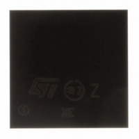
STA015B$ STMicroelectronics, STA015B$ Datasheet - Page 16

STA015B$
Manufacturer Part Number
STA015B$
Description
DECODER AUDIO MPEG 2.5 8X8LFBGA
Manufacturer
STMicroelectronics
Type
Audio Decoderr
Datasheet
1.STA015T.pdf
(56 pages)
Specifications of STA015B$
Applications
Sound Cards, Players, Recorders
Voltage - Supply, Digital
2.4 V ~ 3.6 V
Mounting Type
Surface Mount
Package / Case
64-LFBGA
Lead Free Status / RoHS Status
Lead free / RoHS Compliant
Voltage - Supply, Analog
-
Available stocks
Company
Part Number
Manufacturer
Quantity
Price
Company:
Part Number:
STA015B$13TR
Manufacturer:
STMicroelectronics
Quantity:
10 000
STA015
5.4 READ OPERATION (see Fig. 17)
5.4.1 Current byte address read
The STA015 has an internal byte address counter. Each time a byte is written or read, this counter is in-
cremented. For the current byte address read mode, following a START condition the master sends the
device address with the RW bit set to 1.
The STA015 acknowledges this and outputs the byte addressed by the internal byte address counter. The
master does not acknowledge the received byte, but terminates the transfer with a STOP condition.
5.4.2 Sequential address read
This mode can be initiated with either a current address read or a random address read. However in this
case the master does acknowledge the data byte output and the STA015 continues to output the next byte
in sequence. To terminate the streams of bytes the master does not acknowledge the last received byte,
but terminates the transfer with a STOP condition. The output data stream is from consecutive byte ad-
dresses, with the internal byte address counter automatically incremented after one byte output.
6.0 I
The following table gives a description of the MPEG Source Decoder (STA015) register list.
The first column (HEX_COD) is the hexadecimal code for the sub-address.
The second column (DEC_COD) is the decimal code.
The third column (DESCRIPTION) is the description of the information contained in the register.
The fourth column (RESET) inidicate the reset value if any. When no reset value is specifyed, the default
is "undefined".
The fifth column (R/W) is the flag to distinguish register "read only" and "read and write", and the useful
size of the register itself. Each register is 8 bit wide. The master shall operate reading or writing on 8 bits
only.
I
16/56
2
C REGISTERS
HEX_COD
$40 - $51
2
$0C
$0D
$0F
$00
$01
$05
$06
$07
$10
$13
$14
$16
$18
$40
$41
$42
$43
$44
C REGISTERS
DEC_COD
64 - 81
12
13
15
16
19
20
22
24
64
65
66
67
68
0
1
5
6
7
VERSION
IDENT
PLLCTL [7:0]
PLLCTL [20:16] (MF[4:0]=M)
PLLCTL [15:12] (IDF[3:0]=N)
REQ_POL
SCLK_POL
ERROR_CODE
SOFT_RESET
PLAY
MUTE
CMD_INTERRUPT
DATA_REQ_ENABLE
ADPCM_DATA_1 to ADPCM_DATA_18
SYNCSTATUS
ANCCOUNT_L
ANCCOUNT_H
HEAD_H[23:16]
HEAD_M[15:8]
DESCRIPTION
RESET
0xAC
0xA1
0x0C
0x00
0x01
0x04
0x00
0x00
0x01
0x00
0x00
0x00
0x00
0x00
0x00
0x00
0x00
0x00
R/W (8)
R/W (8)
R/W (8)
R/W (8)
R/W (8)
R/W(8)
R/W(8)
R/W(8)
R/W(8)
W (8)
R (8)
R (8)
R (8)
R (8)
R (8)
R (8)
R (8)
R/W
R(8)
R(8)


