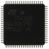
STA310 STMicroelectronics, STA310 Datasheet - Page 17

STA310
Manufacturer Part Number
STA310
Description
IC AUDIO DECODER 6+2CH 80-TQFP
Manufacturer
STMicroelectronics
Type
Audio Decoderr
Datasheet
1.STA310.pdf
(90 pages)
Specifications of STA310
Applications
HDTV, Players, Receivers, Set-Top Boxes
Voltage - Supply, Analog
2.5V
Voltage - Supply, Digital
2.5V
Mounting Type
Surface Mount
Package / Case
80-TQFP, 80-VQFP
Audio Codec Type
MP3 Decoder
No. Of Dacs
3
No. Of Input Channels
2
No. Of Output Channels
6
Adc / Dac Resolution
32bit
Sampling Rate
192kHz
Interface Type
I2C, Serial, Parallel
Rohs Compliant
Yes
Lead Free Status / RoHS Status
Lead free / RoHS Compliant
Other names
497-8856
STA310
STA310
Available stocks
Company
Part Number
Manufacturer
Quantity
Price
Part Number:
STA310
Manufacturer:
ST
Quantity:
20 000
4.4.1.5 Second Input
A second independent input allows to input bitstreams in serial mode.
This second input can be used, to input audio stream from a microphone, while we decode a data stream trough
the main input.
4.4.2 Data parallel interface
Two ways are available to input data in parallel mode:
4.4.2.1 Using the parallel data bus
In this mode the data must be presented on the 8-bit parallel host data bus D[7..0]. Note that this bus is shared
with the external controller. On the rising clock of DSTR the data byte is sampled by the STA310. The signal
REQ is used to signal when the input FIFO is full. When REQ is de-asserted the transfer must be stopped to
avoid data loss.
After the REQ is de-asserted, the decoder is still able to accept data for a limited number of clock cycles.
The maximum number of data that can be transmitted with respect to the change of REQ is given by the follow-
ing formula: Nbits = 23 - 6 * F
The signals DSTR and DCSB are used to make the distinction between Stream Data (strobed by DSTR) and
Control Data (strobed by DCSB). To avoid conflicts, the DSTR signal and the DCSB signal must respect given
timing constraints.
4.4.2.2 Using the DATAIN register
The data can be input by using the control parallel interface as if accessing any other register.
The signal DCSB is therefore used. When using this register to input data stream, there is no need to byte-align
the data.
Figure 8.
- Either through the parallel data bus, shared with the external controller,
- Or through the DATAIN register
LRCLKIN
DSTR
SIN
Transferred data
DSTR
/33MHz, where: F
Discarded data
DSTR
is the DSTR clock frequency, (max is 33 MHz).
STA310
17/90


