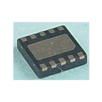
MAX17710G+T Maxim Integrated Products, MAX17710G+T Datasheet - Page 2

MAX17710G+T
Manufacturer Part Number
MAX17710G+T
Description
Battery Management uPower Battery Charger
Manufacturer
Maxim Integrated Products
Datasheet
1.MAX17710GT.pdf
(17 pages)
Specifications of MAX17710G+T
Product
Charge Management
Battery Type
Lithium
Output Voltage
1.8 V, 2.3 V, 3.3 V
Output Current
625 nA
Operating Supply Voltage
5.3 V
Supply Current
50 mA
Maximum Operating Temperature
+ 85 C
Minimum Operating Temperature
- 40 C
Package / Case
DFN-12
Mounting Style
SMD/SMT
Uvlo Start Threshold
3 V
ABSOLUTE MAXIMUM RATINGS
BATT to GND ...........................................................-0.3V to +6V
CHG to GND ...........................................................-0.3V to +6V
LX to PGND .............................................................-0.3V to +6V
GND to PGND ......................................................-0.3V to +0.3V
FB, AE, LCE, SEL1, SEL2, REG,
CHG Continuous Current
Stresses beyond those listed under “Absolute Maximum Ratings” may cause permanent damage to the device. These are stress ratings only, and functional opera-
tion of the device at these or any other conditions beyond those indicated in the operational sections of the specifications is not implied. Exposure to absolute
maximum rating conditions for extended periods may affect device reliability.
ELECTRICAL CHARACTERISTICS
(V
CHG Input Maximum Voltage
CHG Enable Threshold
CHG Quiescent Current
CHG Shunt Delay
CHG Input Shunt Limit
CHG Maximum Input Current
CHG-to-BATT Dropout Voltage
BATT REG
BATT Regulator Voltage
BATT Regulation Delay
BATT Quiescent Current
PCKP to GND .......................................-0.3V to V BATT + 0.3V
(limited by power dissipation of package) ...................100mA
CHG
= +4.3V,
PARAMETER
Figure
����������������������������������������������������������������� Maxim Integrated Products 2
1, T
Energy-Harvesting Charger and Protector
A
= -40NC to +85NC, unless otherwise noted. Typical values are at T
SYMBOL
I
QBATT
I
QCHG
V
CE
Limited by shunt regulator (Note 2)
V
(Note 2)
V
Maximum Ratings
V
V
V
V
V
Regulator in dropout;
V
Harvest standby (AE pulse low)
V
AE regulator on, boost off;
V
LCE regulator on, boost off;
V
CHG
CHG
CHG
CHG
CHG
CHG
CHG
CHG
CHG
CHG
BATT
= 4.0V rising, V
input current limited by Absolute
= 4.0V, I
= 4.0V, I
= 4.0V, I
= 4.0V, I
= 4.2V, starting at 4V
= 4.15V, V
= 0V, V
= 0V, V
= 4.0V, LCE mode (Note 3)
BATT
BATT
CONDITIONS
CHG
BATT
BATT
BATT
BATT
= 2.1V to 4.0V
= 4.0V, AE high
Continuous Power Dissipation (T
Operating Temperature Range .......................... -40NC to +85NC
Junction Temperature .....................................................+150NC
Storage Temperature Range ............................ -65NC to +150NC
Lead Temperature (soldering, 10s) ................................+300NC
Lead Temperature (reflow) ..............................................+260NC
= 1FA
= -6mA
= -20mA
= -40mA
12-Pin UTDFN (derate 15mW/NC above +70NC) .......1200mW
BATT
= 4.12V
= 4.0V
A
4.875
4.065
4.07
MIN
= +25NC.) (Note 1)
50
A
= +70NC)
MAX17710
4.125
TYP
4.15
625
100
100
450
725
150
5.3
25
45
55
65
30
1
4.160
MAX
1300
1030
1650
4.21
165
550
5.7
50
UNITS
mA
mA
mV
nA
nA
Fs
Fs
V
V
V


