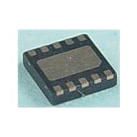
MAX17710G+T Maxim Integrated Products, MAX17710G+T Datasheet - Page 13

MAX17710G+T
Manufacturer Part Number
MAX17710G+T
Description
Battery Management uPower Battery Charger
Manufacturer
Maxim Integrated Products
Datasheet
1.MAX17710GT.pdf
(17 pages)
Specifications of MAX17710G+T
Product
Charge Management
Battery Type
Lithium
Output Voltage
1.8 V, 2.3 V, 3.3 V
Output Current
625 nA
Operating Supply Voltage
5.3 V
Supply Current
50 mA
Maximum Operating Temperature
+ 85 C
Minimum Operating Temperature
- 40 C
Package / Case
DFN-12
Mounting Style
SMD/SMT
Uvlo Start Threshold
3 V
The LDO becomes active when the AE pin is pulsed
above or held above its logic-high threshold, but the
regulator output is not immediately enabled. The device
first charges the external capacitor on PCKP. When the
voltage level on PCKP reaches 3.7V, the regulator output
is enabled in high-current mode. Powering the LDO from
PCKP instead of directly from the cell allows the device
to support large surge or startup inrush currents from the
load that the cell would be unable to handle directly.
Once in high-current mode, the AE pin can remain logic-
high or transition to an open state, and the ouput remains
active. The LDO returns to shutdown only when the AE
pin is driven below its logic-low threshold. Alternatively,
the LDO is transitioned to low-current mode by pulsing
or holding the LCE pin logic-high, followed by pulsing
or holding the AE pin logic-low. Note that the regulator
transitions through a state where both high-current and
low-current modes are active at the same time. While in
low-current mode, the quiescent current drain of the cell
is reduced to 150nA, while the maximum load current
able to be supplied becomes 50FA. Similar to the AE pin
operation, the regulator remains active if the LCE pin is
Figure 5. Regulator Output State Diagram
VCHG > VCE
DETECTED
CHARGE
I
QBATT
POWER-ON RESET (POR)
CHARGE CURRENT
I
I
QBATT
QBATT
SHUTDOWN
���������������������������������������������������������������� Maxim Integrated Products 13
= PCKP CAPACITOR
+ 725nA (typ)
STARTUP
PCKP OFF
PCKP OFF
PCKP ON
REG OFF
REG OFF
REG OFF
RESET
= 1nA (typ)
= 1nA (typ)
Energy-Harvesting Charger and Protector
AE PULSED HIGH
STARTUP FAIL
V
AFTER 5s
PCKP
< 2.15V
V
PCKP
SUCCESS
STARTUP
> 3.7V
AE PULSED LOW
I
QBATT
AE REGULATOR
PCKP ON
ACTIVE
REG ON
= 725nA (typ)
LCE PULSED
LCE PULSED
open or pulled high, and returns to shutdown mode when
LCE is driven below its logic-low threshold.
regulator output state diagram.
If the cell and PCKP capacitance cannot provide sus-
tained support for the load, then the voltage at PCKP col-
lapses. When PCKP collapses, the system load typically
stops and allows the PCKP voltage to recover, resulting
in a perpetual retry in a futile attempt to support a load
that cannot be supported. When PCKP fails in this way,
the device shuts off the REG output to prevent futile load
retries and protect the cell from overdischarge. When the
REG output is latched off, the BATT quiescent current
reduces to 1nA (typ). Once UVLO occurs, the regulator
output remains disabled until the device detects that a
charge source has been connected to the system (V
> 4.15V).
Connecting any load to REG or PCKP instead of connect-
ing directly to the cell is highly recommended. This con-
trols the quiescent current during shutdown, enables the
device to support startup during cold, and also protects
the cell from overdischarge.
HIGH
LOW
LCE PULSED LOW
V
V
CELL UNDERVOLTAGE PROTECTION
PCKP
PCKP
Figure 6
REGULATORS ACTIVE
< 2.15V (HIGH-CURRENT MODE)
< 3.0V (LOW-CURRENT MODE)
I
QBATT
AE AND LCE
AFTER 500µs
PCKP ON
REG ON
= 875nA (typ)
shows the UVLO protection modes.
Cell Undervoltage Lockout (UVLO)
AE PULSED
AE PULSED
HIGH
LOW
MAX17710
I
LCE REGULATOR
QBATT
Figure 5
PCKP ON
ACTIVE
REG ON
= 150nA (typ)
is the
CHG


