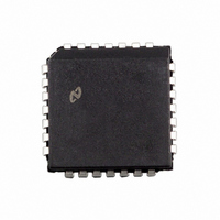
DP8392CV National Semiconductor, DP8392CV Datasheet - Page 2

DP8392CV
Manufacturer Part Number
DP8392CV
Description
IC TRANSCEIVER COAX INT 28-PLCC
Manufacturer
National Semiconductor
Series
DPr
Type
Transceiverr
Datasheet
1.DP8392CV.pdf
(12 pages)
Specifications of DP8392CV
Number Of Drivers/receivers
1/1
Protocol
IEEE 802
Voltage - Supply
9V
Mounting Type
Surface Mount
Package / Case
*
Lead Free Status / RoHS Status
Contains lead / RoHS non-compliant
Other names
*DP8392CV
Available stocks
Company
Part Number
Manufacturer
Quantity
Price
Company:
Part Number:
DP8392CV
Manufacturer:
NSC
Quantity:
1 995
Part Number:
DP8392CV
Manufacturer:
NS/国半
Quantity:
20 000
Company:
Part Number:
DP8392CV-1
Manufacturer:
NSC
Quantity:
1 584
Company:
Part Number:
DP8392CV-1
Manufacturer:
Texas Instruments
Quantity:
10 000
Part Number:
DP8392CV-1
Manufacturer:
NS/国半
Quantity:
20 000
Company:
Part Number:
DP8392CV-2
Manufacturer:
NSC
Quantity:
5 510
Company:
Part Number:
DP8392CV-2
Manufacturer:
CDC
Quantity:
5 510
Part Number:
DP8392CV-2
Manufacturer:
HARRIS
Quantity:
20 000
Part Number:
DP8392CVX
Manufacturer:
NS/国半
Quantity:
20 000
2 0 Block Diagram
3 0 Functional Description
The CTI consists of four main logical blocks
a) the Receiver - receives data from the coax and sends it
b) the Transmitter - accepts data from the DTE and trans-
c) the Collision Detect circuitry - indicates to the DTE any
d) the Jabber Timer - disables the Transmitter in case of
3 1 RECEIVER FUNCTIONS
The Receiver includes an input buffer a cable equalizer a
4-pole Bessel low pass filter a squelch circuit and a differ-
ential line driver
The buffer provides high input impedance and low input ca-
pacitance to minimize loading and reflections on the coax
The equalizer is a high pass filter which compensates for
the low pass effect of the cable The composite result of the
maximum length cable and the equalizer is a flatband re-
sponse at the signal frequencies to minimize jitter
The 4-pole Bessel low pass filter extracts the average DC
level on the coax which is used by both the Receiver
squelch and the collision detection circuits
The Receiver squelch circuit prevents noise on the coax
from falsely triggering the Receiver in the absence of the
signal At the beginning of the packet the Receiver turns on
when the DC level from the low pass filter is lower than the
DC squelch threshold However at the end of the packet a
quick Receiver turn off is needed to reject dribble bits This
is accomplished by an AC timing circuit that reacts to high
level signals of greater than typically 200 ns in duration The
to the DTE
mits it onto the coax
collision on the coax
longer than legal length packets
FIGURE 1 DP8392C Block Diagram
2
Receiver then stays off only if within about 1
level from the low pass filter rises above the DC squelch
threshold Figure 2 illustrates the Receiver timing
The differential line driver provides ECL compatible signals
to the DTE with typically 3 ns rise and fall times In its idle
state its outputs go to differential zero to prevent DC stand-
ing current in the isolation transformer
3 2 TRANSMITTER FUNCTIONS
The Transmitter has a differential input and an open collec-
tor output current driver The differential input common
mode voltage is established by the CTI and should not be
altered by external circuitry The transformer coupling of
TX
802 3 Ethernet Specifications for signal levels Controlled
rise and fall times (25 ns V
harmonic components The rise and fall times are matched
to minimize jitter The drive current levels of the DP8392C
meet the tighter recommended limits of IEEE 802 3 and are
set by a built-in bandgap reference and an external 1% re-
sistor An on chip isolation diode is provided to reduce the
Transmitter’s coax load capacitance For Ethernet compati-
ble applications an external isolation diode (see Figure 4 )
may be added to further reduce coax load capacitance In
Cheapernet compatible applications the external diode is
not required as the coax capacitive loading specifications
are relaxed
The Transmitter squelch circuit rejects signals with pulse
widths less than typically 20 ns (negative going) or with
levels less than
end of the packet if the signal stays higher than
for more than approximately 300 ns Figure 3 illustrates the
Transmitter timing
g
will satisfy this condition The driver meets all IEEE
b
175 mV The Transmitter turns off at the
g
5 ns) minimize the higher
TL F 11085 – 2
b
s the DC
175 mV


