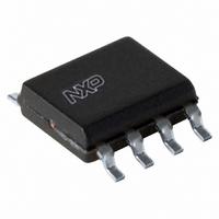
AU5780AD,118 NXP Semiconductors, AU5780AD,118 Datasheet - Page 5

AU5780AD,118
Manufacturer Part Number
AU5780AD,118
Description
IC TXRX SAE/J1850 VPW 8SOIC
Manufacturer
NXP Semiconductors
Series
AUr
Type
Transceiverr
Datasheet
1.AU5780AD112.pdf
(12 pages)
Specifications of AU5780AD,118
Package / Case
8-SOIC (3.9mm Width)
Number Of Drivers/receivers
1/1
Voltage - Supply
6 V ~ 24 V
Mounting Type
Surface Mount
Mounting Style
SMD/SMT
Lead Free Status / RoHS Status
Lead free / RoHS Compliant
Protocol
-
Lead Free Status / RoHS Status
Lead free / RoHS Compliant, Lead free / RoHS Compliant
Other names
935263103118
AU5780AD-T
AU5780AD-T
AU5780AD-T
AU5780AD-T
1. RX outputs the bus state. If the bus level is below the receiver threshold (i.e., all transmitters passive), then RX will be floating (i.e., high,
1. For bus voltages –20V < V
Philips Semiconductors
CONTROL INPUT SUMMARY
NOTE:
ABSOLUTE MAXIMUM RATINGS
According to the IEC 134 Absolute Maximum System; operation is not guaranteed under these conditions; all voltages are referenced to pin 8
(GND); positive currents flow into the IC; unless otherwise specified.
NOTE:
2001 Jun 19
V
V
V
V
V
V
V
V
V
V
ESD
ESD
ESD
P
T
T
T
T
I
I
CL(BUS)
CL(BATT)
amb
stg
vj
LEAD
BATT
BATT.ld
BATT.tr1
BATT.tr2
BATT.tr3
B
B.tr1
B.tr2
B.tr3
I
tot
SAE/J1850/VPW transceiver
JA
considering external pull-up resistance). Otherwise, if the bus level is above the receiver threshold (i.e., at least one transmitter is active),
then RX will be low.
TX
SYMBOL
0
1
0
1
BATT
bus
logic
/LB
0
0
1
1
supply voltage
short-term supply voltage
transient supply voltage
transient supply voltage
transient supply voltage
Bus voltage
transient bus voltage
transient bus voltage
transient bus voltage
DC voltage on pins TX, R/F, RX, /LB
ESD capability of BATT pin
ESD capability of BUS_OUT and BUS_IN pins
ESD capability of TX, RX, R/F, and /LB pins
maximum power dissipation
thermal impedance
operating ambient temperature
storage temperature
junction temperature
Lead temperature
Bus output clamp current
Battery clamp current
Loop-back
Loop-back
Communication
Communication
bus
< –17V and +17V < V
PARAMETER
MODE
bus
< +20V the current is limited by the external resistors R
TX passive (default state)
TX active
Transmitter passive
Transmitter active
load dump; t < 1s
SAE J1113 pulse 1
SAE J1113 pulses 2
SAE J1113 pulses 3A, 3B
R
SAE J1113 pulse 1
SAE J1113 pulses 2
SAE J1113 pulses 3A, 3B
Air gap discharge,
R=2k , C=150pF
Air gap discharge,
R=2k , C=150pF, R
Human Body,
R=1.5k , C=100pF
at T
Soldering, 10 seconds maximum
No latch-up, |V
No latch-up or snap back,
|V
f
BATT
> 10 k ; Rb >10
5
amb
BIT VALUE
| = 25 V
= +125 C
CONDITIONS
BUS
| = 25 V
f
> 10 k
1
BUS_OUT
–20
–100
–200
–20
–50
–200
–0.3
–9
–9
–2
–40
–40
–40
float
float
float
high
MIN.
b
and R
+24
+50
+150
+200
+20
+100
+200
7
+9
+9
+2
164
152
+125
+150
+150
265
100
100
f
MAX.
.
AU5780A
float (high)
bus state
(out)
low
low
RX
Product data
V
V
V
V
V
V
V
V
V
V
kV
kV
kV
mW
mA
mA
C/W
C
C
C
C
UNIT
1


