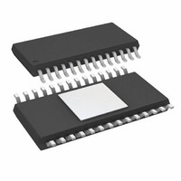
AD8392ARE Analog Devices Inc, AD8392ARE Datasheet - Page 14

AD8392ARE
Manufacturer Part Number
AD8392ARE
Description
IC LINE DRVR ADSL/ADSL2 28TSSOP
Manufacturer
Analog Devices Inc
Type
Driverr
Datasheet
1.AD8392AREZ-REEL.pdf
(16 pages)
Specifications of AD8392ARE
Number Of Drivers/receivers
2/0
Protocol
xDSL
Voltage - Supply
5 V ~ 24 V
Mounting Type
Surface Mount
Package / Case
28-TSSOP Exposed Pad, 28-eTSSOP, 28-HTSSOP
Power Supply Requirement
Single/Dual
Package Type
TSSOP EP
Slew Rate
900V/us
Pin Count
28
Lead Free Status / RoHS Status
Contains lead / RoHS non-compliant
Available stocks
Company
Part Number
Manufacturer
Quantity
Price
Company:
Part Number:
AD8392ARE
Manufacturer:
AD
Quantity:
5 510
Company:
Part Number:
AD8392ARE
Manufacturer:
TOS
Quantity:
5 510
Part Number:
AD8392AREZ
Manufacturer:
ADI/亚德诺
Quantity:
20 000
AD8392
Additional definitions for calculating resistor values include:
V
k
A
β
α
Note: R1 must be calculated before β and α.
With the above known quantities and definitions, the remaining
resistors can readily be calculated.
After building the circuit with the closest 1% resistor values,
the actual gain, input resistance, and output resistance can be
verified with the following equations.
OA
V
V
β
GAIN
R1
R4
R3
R
R
R
OA
OUT
BIAS
IN
=
=
=
=
R1
=
=
V
R
A
2
=
(
=
V
OA
V
+
IN
V
R4
R1
V
Voltage at the amplifier outputs
Matching resistance reduction factor
Gain from V
Negative feedback factor
Positive feedback factor
IN
1
1
R4
LINE
2
R4
P
(
−
−
to
2
R2
V
−
R
V
V
−
⎛
⎜
⎜
⎝
LINE
N
IN
(
A
2
2
α
(
R1
P
IN
α
1
V
R1
R3
−
(
+
β
R3
(
)
R4
V
R4
k
R
⎛
⎜
⎜
⎝
R4
=
2
P
)
m
2
+
β
IN
R
)
+
α
R
R4
+
R4
(
BIAS
to transformer primary
m
R
k
R
R1
L
+
BIAS
R
)
+
(
2
1
L
R1
R
R
R
)
L
k
⎛
⎜
⎝
L
m
)
1
+
−
=
⎞
⎟
⎟
⎠
⎞
⎟
⎟
⎠
+
N
⎛
⎜
⎜
⎜
⎜
⎝
2
α
2
R3
R2
R4
R3
2
R
R1
R
L
N
m
)
+
R
+
R1
L
R4
R
R4
+
−
R4
BIAS
+
2α
2
R
R2
R
BIAS
R2
BIAS
⎞
⎟
⎠
−
R
A =
R4
R3
L
V
α
⎞
⎟
⎟
⎟
⎟
⎠
)
= 1
β
N
V
(
LINE
V
−
Rev. A | Page 14 of 16
IN
k
)
MULTITONE POWER RATIO
The DMT signal used in ADSL/ADSL2+ systems carries data in
discrete tones or bins, which appear in the frequency domain in
evenly spaced 4.3125 kHz intervals. In applications using this
type of waveform, multitone power ratio (MTPR) is a com-
monly used measure of linearity. Generally, there are two types
of MTPR that designers are typically concerned with: in-band
and out-of-band MTPR. In-band MTPR is defined as the
measured difference from the peak of one tone that is loaded
with data to the peak of an adjacent tone that is intentionally
left empty. Out-of-band MTPR is more loosely defined as the
spurious emissions that occur in the receive band located
between 25.875 kHz and the first downstream tone at 138 kHz.
Figure 38 and Figure 39 show the AD8392 in-band MTPR for a
5.5 crest factor waveform for empty bins in the ADSL and
extended ADSL2+ bandwidths. Figure 40 shows the AD8392
out-of-band MTPR for the same waveform.
–100
–110
–120
–100
–110
–120
–20
–30
–40
–50
–60
–70
–80
–90
–20
–30
–40
–50
–60
–70
–80
–90
CENTER 1.75MHz
CENTER 647kHz
Figure 39. In-Band MTPR at 1.751 MHz
Figure 38. In-Band MTPR at 647 kHz
72.2dB
64.4dB
1kHz/
1kHz/
SPAN 10kHz
SPAN 10kHz


