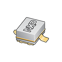
BLA1011-2 NXP Semiconductors, BLA1011-2 Datasheet - Page 2

BLA1011-2
Manufacturer Part Number
BLA1011-2
Description
MOSFET Power BULK TNS-MICP
Manufacturer
NXP Semiconductors
Datasheet
1.BLA1011-2.pdf
(9 pages)
Specifications of BLA1011-2
Configuration
Single
Transistor Polarity
N-Channel
Resistance Drain-source Rds (on)
1.2 Ohms
Drain-source Breakdown Voltage
75 V
Gate-source Breakdown Voltage
+/- 15 V
Continuous Drain Current
2.2 A
Power Dissipation
10 W
Maximum Operating Temperature
+ 200 C
Mounting Style
SMD/SMT
Package / Case
SOT-538A
Minimum Operating Temperature
- 65 C
Lead Free Status / Rohs Status
Details
Other names
BLA1011-2,112
Available stocks
Company
Part Number
Manufacturer
Quantity
Price
Company:
Part Number:
BLA1011-2
Manufacturer:
NXP
Quantity:
1 000
Company:
Part Number:
BLA1011-2
Manufacturer:
NXP
Quantity:
5 000
Part Number:
BLA1011-2
Manufacturer:
NXP/恩智浦
Quantity:
20 000
Company:
Part Number:
BLA1011-200
Manufacturer:
NXP
Quantity:
1 000
Company:
Part Number:
BLA1011-200
Manufacturer:
NXP
Quantity:
1 400
Part Number:
BLA1011-200
Manufacturer:
NXP/恩智浦
Quantity:
20 000
Company:
Part Number:
BLA1011-200R
Manufacturer:
NXP
Quantity:
1 000
Philips Semiconductors
FEATURES
APPLICATIONS
DESCRIPTION
Silicon N-channel enhancement mode lateral D-MOS
transistor encapsulated in a 2-lead flangeless package
(SOT538A) with a ceramic cap. The common source is
connected to the mounting base.
QUICK REFERENCE DATA
RF performance at T
ORDERING INFORMATION
LIMITING VALUES
In accordance with the Absolute Maximum Rating System (IEC 60134).
2003 Nov 19
Pulsed class-AB;
t
BLA1011-2
V
V
I
P
T
T
p
D
SYMBOL
stg
j
High power gain
Easy power control
Excellent ruggedness
Source on mounting base eliminates DC isolators,
reducing common mode inductance.
Avionics applications in the 1030 to 1090 MHz
frequency range.
DS
GS
tot
Avionics LDMOS transistor
TYPE NUMBER
MODE OF OPERATION
= 50 s;
= 2%
drain-source voltage
gate-source voltage
drain current (DC)
total power dissipation
storage temperature
junction temperature
h
= 25 C in a common source test circuit.
PARAMETER
NAME
1030 to 1090
(MHz)
f
ceramic surface mounted package; 2 leads
T
h
25 C
2
PINNING - SOT538A
V
(V)
CONDITIONS
36
DS
PACKAGE
DESCRIPTION
PIN
1
2
3
Fig.1 Simplified outline (SOT538A).
Top view
drain
gate
source, connected to mounting base
(W)
P
1
2
2
L
65
MIN.
DESCRIPTION
Product specification
3
75
2.2
10
+150
200
BLA1011-2
15
MAX.
MBK905
(dB)
>16
G
VERSION
SOT538A
p
V
V
A
W
C
C
UNIT


