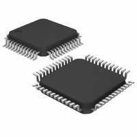
DS3150TN+ Maxim Integrated Products, DS3150TN+ Datasheet - Page 22

DS3150TN+
Manufacturer Part Number
DS3150TN+
Description
IC LIU T3/E3/STS-1 48-TQFP
Manufacturer
Maxim Integrated Products
Type
Line Interface Units (LIUs)r
Datasheet
1.DS3150T.pdf
(28 pages)
Specifications of DS3150TN+
Number Of Drivers/receivers
1/1
Protocol
DS3
Voltage - Supply
3.135 V ~ 3.465 V
Mounting Type
Surface Mount
Package / Case
48-LQFP
Lead Free Status / RoHS Status
Lead free / RoHS Compliant
FRAMER INTERFACE TIMING
(V
Figure 3-1. Framer Interface Timing Diagram
Note 4:
Note 5:
Note 6:
Note 7:
Note 8:
RCLK/TCLK Clock Period
RCLK Clock High/Low Time
TCLK Clock High/Low Time
TPOS/TNRZ, TNEG to TCLK
Setup Time
TPOS/TNRZ, TNEG Hold
Time
RCLK to RPOS/RNRZ Valid,
RNEG/RLCV Valid, State
Change on PRBS
DD
= 3.3V ±5%, T
RCLK (normal mode),
TCLK (inverted mode)
TCLK (normal mode),
RCLK (inverted mode)
RNEG/RLCV, PRBS
TPOS/TNRZ, TNEG
PARAMETER
DS3 mode.
E3 mode.
STS-1 mode.
In normal mode, TPOS/TNRZ and TNEG are sampled on the rising edge of TCLK and RPOS/RNRZ and RNEG/RLCV are
updated on the falling edge of RCLK.
In inverted mode, TPOS/TNRZ and TNEG are sampled on the falling edge of TCLK and RPOS/RNRZ and RNEG/RLCV are
updated on the rising edge of RCLK.
RPOS/RNRZ,
A
= 0°C to +70°C for DS3150Q/T, T
SYMBOL
t2, t3
t2, t3
t1
t4
t5
t6
t2
(Note 4)
(Note 5)
(Note 6)
(Note 4)
(Note 5)
(Note 6)
(Notes 7, 8)
CONDITIONS
t4
22 of 28
A
= -40°C to +85°C for DS3150QN/TN.)
t1
t5
t6
MIN
t3
11.6
9.0
7.7
7
2
2
2
TYP
22.4
29.1
19.3
11.2
14.5
9.6
MAX
13.4
17.4
11.5
(Figure
6
3-1)
UNITS
ns
ns
ns
ns
ns
ns


