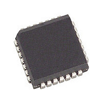
NLXT905PE.C2 Cortina Systems Inc, NLXT905PE.C2 Datasheet - Page 8

NLXT905PE.C2
Manufacturer Part Number
NLXT905PE.C2
Description
Manufacturer
Cortina Systems Inc
Datasheet
1.NLXT905PE.C2.pdf
(35 pages)
Specifications of NLXT905PE.C2
Number Of Receivers
1
Data Rate
10Mbps
Operating Supply Voltage (typ)
5V
Package Type
PLCC
Operating Temperature Classification
Industrial
Operating Supply Voltage (max)
5.25V
Mounting
Surface Mount
Pin Count
28
Operating Temperature (max)
85C
Operating Temperature (min)
-40C
Lead Free Status / Rohs Status
Not Compliant
Available stocks
Company
Part Number
Manufacturer
Quantity
Price
LXT905 Transceiver
Datasheet
249271, Revision 5.1
5 November 2007
Table 1
Cortina Systems
1. Externally pull-up or pull-down each pin separately using a 10 k Ω, 1% termination resistor, or tie directly to V
2. Do not allow this pin to float. If unused, tie High.
Pin #
LQFP
10
14
15
16
17
18
19
22
23
24
25
26
6
7
8
9
PLCC
Pin #
10
12
13
14
16
17
18
19
20
21
24
25
26
27
28
11
LXT905 Transceiver Signal Descriptions (Sheet 2 of 2)
®
LXT905 Universal 10BASE-T Transceiver with 3.3 V Support
Symbol
LEDC/
RBIAS
LEDT/
DSQE
TPOP
TPON
LEDR
RCLK
LEDL
MDO
TPIN
PDN
RXD
TPIP
FDE
MDI
CD
LI
I/O
O
O
O
O
O
O
O
O
O
I
I
I
I
I
I
I
I
I
LED Collision or Full Duplex Enable.
LEDC is an open drain driver for the collision indicator, and pulls Low during
collision. Extends LED “on” (which is Low output) time by approximately 100 ms.
FDE enables full duplex mode (external loopback) if tied Low externally. Pulled
High internally
LED Transmit or Power Down.
LEDT is an open drain driver for the transmit indicator. Extends LED “on” (which
is Low output) time by approximately 100 ms. Pulls output Low during transmit
If externally tied Low, the LXT905 goes to power down state (PDN). In power-
down mode, LEDT trislates all logic inputs and outputs.
LED Receive. Open drain driver for the receive indicator LED. Extends LED
“on” (which is Low output) time by approximately 100 ms. Pulls output Low
during receive. Pulled High internally
LED Link. Open drain driver for link integrity indicator. Pulls output Low during
link test pass. Pulled High internally
Carrier Detect. An output for notifying the controller that activity exists on the
network.
Receive Clock. A recovered 10 MHz clock that is synchronous to the received
data and connects to the controller receive clock input.
Receive Data. Output signal connected directly to the receive data input of the
controller.
Link Enable. Controls link integrity test
Bias Circuitry. A 7.5 kW 1% resistor to ground at this pin controls operating
circuit bias.
SQE Disable.
Disable SQE for normal operation in Hub/Switch/Repeater applications. Pulled
Low internally
Twisted-Pair Outputs. Differential outputs to the twisted-pair cable. The outputs
are pre-equalized.
Mode Select 0 and 1. Mode select pins determine controller compatibility mode
in accordance with
Twisted-Pair Inputs. A differential input pair from the twisted-pair cable.
Receive filter is integrated on-chip. Does not require external filters.
• Enabled when LI is High
• Disabled when LI is Low
• When DSQE is High, the SQE function is disabled.
• When DSQE is Low, the SQE function is enabled.
1
1
.
.
Table
2. Pulled Low internally
Description
1
.
1
.
1.0 Pin Assignments and Signal
1
.
CC
Descriptions
or ground.
Page 8
2
.


