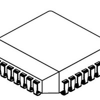
NJM3771FM2-TE3 NJR, NJM3771FM2-TE3 Datasheet - Page 8

NJM3771FM2-TE3
Manufacturer Part Number
NJM3771FM2-TE3
Description
Motor / Motion / Ignition Controllers & Drivers Dual Stepper Motor Driver
Manufacturer
NJR
Type
Stepper Motor Controller/Driverr
Datasheet
1.NJM3771FM2.pdf
(9 pages)
Specifications of NJM3771FM2-TE3
Product
Stepper Motor Controllers / Drivers
Operating Supply Voltage
10 V to 45 V
Supply Current
38 mA to 50 mA
Mounting Style
SMD/SMT
Package / Case
PLCC-28
Lead Free Status / Rohs Status
Lead free / RoHS Compliant
General
Phase inputs
A logic HIGH on a Phase input gives positive current flowing out from M
the opposite direction.
Slow/fast current decay
Heat sinking
Soldering the four center pins onto a free PCB copper area of 20 cm
35 m) permits the circuit to operate with a maximum of 320 mA output current, both channels driving, at ambient
temperatures up to +70 C. Consult figures 9 and 14 in order to determine the necessary copper area for heat
sinking if higher currents are required.
Thermal shutdown
The circuit is equipped with a thermal shutdown function that reduces the output current at chip temperatures
above +160 C.
Figure 9. Thermal Resistance vs. PC Board copper area and suggested layout
A logic HIGH on the CD input gives slow current decay, a logic LOW gives fast current decay.
80
70
60
50
40
30
20
Thermal resistance [ C/W]
PLCC package
DIP package
5
PCB copper foil area [cm ]
10
15
20
25
2
30
35
24-pin EMP
2
(approx. 1.8" x 1.8", copper foil thickness =
A
into M
B
. A logic LOW gives a current in
22-pin
28-pin
PLCC
DIP
NJM3771


