NJM3771FM2-TE3 NJR, NJM3771FM2-TE3 Datasheet
NJM3771FM2-TE3
Specifications of NJM3771FM2-TE3


Related parts for NJM3771FM2-TE3


NJM3771FM2-TE3 Summary of contents
Page 1
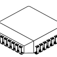
... Specially matched to Dual DAC NJU39610 • Packages DIP22 / EMP24(Batwing) / PLCC28 BLOCK DIAGRAM NJM 3771 Figure 1. Block diagram DUAL STEPPER MOTOR DRIVER Phase – – + – – – Phase GND NJM3771 PACKAGE OUTLINE NJM3771E3 NJM3771D2 NJM3771FM2 Logic MM1 V MM2 M B2 Logic ...
Page 2
...
Page 3
FUNCTIONAL DESCRIPTION Each channel of the NJM3771 consists of the following sections: an H-bridge output stage, capable of driving up to 650 mA continuous motor current (or 500 mA, both channels driven), a logic section that controls the output transistors, ...
Page 4
ABSOLUTE MAXIMUM RATINGS Parameter Voltage Logic supply Motor supply Logic inputs Comparator inputs Reference inputs Current Motor output current Logic inputs Analog inputs Oscillator charging current Temperature Operating junction temperature Storage temperature** ** Circuit only. The packaging can handle max ...
Page 5
ELECTRICAL CHARACTERISTICS Electrical characteristics over recommended operating conditions, unless otherwise noted. -20 C < T Parameter General Supply current Total power dissipation Turn-off delay Logic Inputs Logic HIGH input voltage Logic LOW input voltage Logic HIGH input current Logic LOW ...
Page 6
APPLICATIONS INFORMATION Current control The output current to the motor winding is mainly determined by the voltage at the reference input and the value of the sensing resistor Chopping frequency, winding inductance, and supply voltage will affect ...
Page 7
External components The voltage across the sensing resistor is fed back to the comparator via a low-pass filter section, to prevent erroneous switching due to switching transients. The recommended filter component values, 1 kohm and 820 pF, are suitable for ...
Page 8
General Phase inputs A logic HIGH on a Phase input gives positive current flowing out from M the opposite direction. Slow/fast current decay A logic HIGH on the CD input gives slow current decay, a logic LOW gives fast current ...
Page 9
TYPICAL CHARACTERISTICS 125 .10 .20 .30 .40 .50 .60 I (A) M Figure 10. Typical upper diode voltage drop vs. recirculating ...