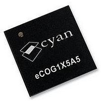
ECOG1X5A5L CYAN, ECOG1X5A5L Datasheet - Page 52

ECOG1X5A5L
Manufacturer Part Number
ECOG1X5A5L
Description
MCU, 16BIT, 512K FLASH, USB, 68QFN
Manufacturer
CYAN
Datasheet
1.ECOG1X5A5L.pdf
(95 pages)
Specifications of ECOG1X5A5L
Core Size
16bit
No. Of I/o's
32
Program Memory Size
512KB
Ram Memory Size
24KB
Cpu Speed
70MHz
Oscillator Type
External, Internal
No. Of Timers
5
No. Of Pwm Channels
2
Rohs Compliant
Yes
Controller Family/series
ECOG1X
Version 1.17
52
•
•
•
•
For low power operation, note the following additional recommendations.
•
•
The eICE_LOADB pin must be connected to VDD via a 100kΩ pull-up resistor for normal
operation when the eICE debug port is not in use or disconnected. When the eICE port is used for
debugging, a 4.7kΩ pull-up resistor is required. If the system is used with an external eICE
programming adaptor, then the external adaptor has the 4.7kΩ pull-up resistor fitted, and the
The target system circuit board must make the eICE debug port connections available
for software development, debugging and downloading into flash memory. Usually
these signals are brought to a connector or pin header. A 10-way boxed header is
preferred, as this provides mechanical polarisation and is compatible with the Cyan
USB eICE debug adaptor. Suggested connections for this 10-way header on an
eCOG1X target system are shown in the diagram below.
The VPP pin is used with a higher voltage supply to support faster programming of the internal
flash memory via JTAG. If this function is not required, then the VPP pin should be connected to
GND to minimise power consumption in normal operation. If this function is required, then
connect VPP to GND via a pull-down resistor or jumper link so that the fast programming supply
can be connected.
NC indicates a No Connect. Any pins labelled as NC should not be connected in circuit.
All digital input pins and bidirectional port pins have Schmitt trigger input circuits.
The EMI data bus pins float as inputs in the sleep state and can cause higher than expected
power consumption. If minimum power consumption in the sleep state is required, connect all the
EMI data bus pins to GND or to VDD via 100kΩ resistors.
Similarly, all unused port input pins should be connected to GND or to VDD via 100kΩ resistors to
target system only needs a 100kΩ pull-up resistor connected to this signal.
It is also recommended that the eICE input signals (eICE_CLK, eICE_MOSI) are connected to
GND via 100kΩ pull-down resistors as a precaution against noise.
prevent them floating.
+1.8V
eCOG1X
eCOG and CyanIDE are registered trademarks of Cyan Holdings plc
GND
+3.3V
eCOG1X Microcontroller Product Family
Figure 6: eICE debug header connections
eICE_MOSI
eICE_LOADB
eICE_CLOCK
eICE_MISO
nReset
www.cyantechnology.com
+3.3V
GND
(not used)
eICE_CS
small signal diode
eICE header
1
3
5
7
9
10
2
4
6
8
eICE_nReset
+5V (optional)
GND
11 February 2010


