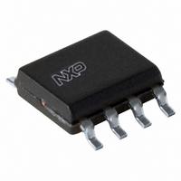
TDA8579T/N1,118 NXP Semiconductors, TDA8579T/N1,118 Datasheet - Page 5

TDA8579T/N1,118
Manufacturer Part Number
TDA8579T/N1,118
Description
IC DUAL DIFF LINE RCVR 8-SOIC
Manufacturer
NXP Semiconductors
Type
Receiverr
Datasheet
1.TDA8579TN1112.pdf
(13 pages)
Specifications of TDA8579T/N1,118
Package / Case
8-SOIC (3.9mm Width)
Number Of Drivers/receivers
0/2
Voltage - Supply
5 V ~ 18 V
Mounting Type
Surface Mount
Number Of Channels
Dual
Common Mode Rejection Ratio (min)
66 dB
Available Set Gain
0.5 dB
Operating Supply Voltage
8.5 V
Supply Current
14 mA
Maximum Operating Temperature
+ 85 C
Minimum Operating Temperature
- 40 C
Mounting Style
SMD/SMT
Supply Voltage (max)
18 V
Supply Voltage (min)
5 V
Lead Free Status / RoHS Status
Lead free / RoHS Compliant
Protocol
-
Lead Free Status / Rohs Status
Lead free / RoHS Compliant
Other names
935075970118
TDA8579TD-T
TDA8579TD-T
TDA8579TD-T
TDA8579TD-T
Philips Semiconductors
CHARACTERISTICS
V
Notes
1. The DC output voltage with respect to ground is approximately 0.5V
2. The frequency response is externally fixed by the input coupling capacitors.
3. The noise output voltage is measured in a bandwidth of 20 Hz to 20 kHz (unweighted).
4. The common-mode rejection ratio is measured at the output with a voltage source 1 V (RMS) in accordance with the
5. The ripple rejection is measured at the output, with R
6. The ripple rejection is measured at the output, with R
1995 Dec 15
V
I
V
t
G
f
f
V
V
V
CMRR
SVRR
THD
THD
CC
set
L
H
CC
Z
Z
CC
O
cs
i(max)
no
CM(rms)
Dual common-mode rejection
differential line receiver
v
SYMBOL
G
i
o
test circuit (see Fig.3) while V
amplitude of 2 V (p-p).
= 8.5 V; T
v
max
amb
supply voltage
supply current
DC output voltage
DC input voltage settling time
voltage gain
channel separation
channel unbalance
low frequency roll-off
high frequency roll-off
input impedance
output impedance
maximum input voltage
noise output voltage
common-mode input voltage
(RMS value)
common-mode rejection ratio
supply voltage ripple rejection
total harmonic distortion
total harmonic distortion at
maximum output current
= 25 C; f = 1 kHz; measured in test circuit of Fig.3; unless otherwise specified.
PARAMETER
INL
and V
INR
are short-circuited. Frequencies between 100 Hz and 100 kHz.
note 1
R
THD = 1%
R
R
R
note 5
note 6
V
V
f = 20 Hz to 20 kHz
V
1 dB; note 2
1 dB
i
i
i
s
s
s
s
= 1 V;
= 1 V;
= 1 V; R
= 5 k
= 0 ; note 3
= 5 k
= 0 ; note 4
CONDITIONS
s
s
= 2 k , f = 1 kHz and a ripple amplitude of 2 V (p-p).
= 0 to 2 k , f = 100 Hz to 20 kHz and a maximum ripple
5
L
= 150
CC
.
5.0
70
20
20
100
66
55
0.5
MIN.
8.5
11
4.3
0.2
0
80
240
2.0
3.7
70
80
65
60
0.02
TYP.
Product specification
18
14
+0.5
0.5
10
5.0
1.0
0.1
1
MAX.
TDA8579
V
mA
V
s
dB
dB
dB
Hz
kHz
k
V
V
dB
dB
dB
dB
%
%
%
V
UNIT


