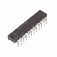
MAX1490EBCPG+ Maxim Integrated Products, MAX1490EBCPG+ Datasheet - Page 18

MAX1490EBCPG+
Manufacturer Part Number
MAX1490EBCPG+
Description
IC RS485/RS422 DATA INTRFC 24DIP
Manufacturer
Maxim Integrated Products
Type
Transceiverr
Datasheet
1.MAX1480ECEPI.pdf
(19 pages)
Specifications of MAX1490EBCPG+
Number Of Drivers/receivers
1/1
Protocol
RS422, RS485
Voltage - Supply
4.5 V ~ 5.5 V
Mounting Type
Through Hole
Package / Case
24-DIP (0.600", 15.24mm)
Data Rate
250 Kbps
Operating Supply Voltage
5 V
Supply Current
130 mA
Operating Temperature Range
0 C to + 70 C
Maximum Power Dissipation
696 mW
Mounting Style
Through Hole
Lead Free Status / RoHS Status
Lead free / RoHS Compliant
rents may flow. These currents are by their nature unsta-
ble and unpredictable. In addition, they may cause noise
to be injected into sensitive instrumentation and, in
severe cases, might actually cause physical damage to
such equipment.
Figure 17 shows a half-duplex (2-wire), bidirectional,
party-line repeater system that prevents interference
and/or damage from ground-potential differences. Two
MAX1480EA/MAX1480EC isolated RS-485 transceivers
are used to isolate each of the network segments from
the electrical environment of the repeater. The
MAX1480EA/MAX1480EC also regenerate bus signals
that may have been degraded by line attenuation or dis-
persion.
In the idle state, both transmitters are disabled, while all
receivers in the system are enabled. If any device on the
system has information for any other device, it starts
sending its data onto the bus. Each data transmission on
the bus retriggers the one-shot, keeping the sending
transmitter enabled until there are no more transmis-
sions. All receivers receive all data; if this is undesirable,
the protocol must allow for an address field so receivers
can ignore data not directed to them.
Each node must refrain from transmitting when data
already exists on the bus, and must resend data that is
±15kV ESD-Protected, Isolated RS-485/RS-422
Data Interfaces
Figure 17. Double-Isolated RS-485 Repeater
18
______________________________________________________________________________________
NETWORK SEGMENT A
3kΩ
200Ω
A
B
3kΩ
23
25
26
15
19
22
17
21
24
MAX1480EC
+5V
2 8
5 7 12
10 14
11
13
9
2 B
1
+5V
A
200Ω
200Ω
16
51kΩ
74HC123
CLR
3kΩ
3
1000pF
DRIVER
ENABLE
B > A
15
Q
Q
14
13
4
4
1
74HC04
3
corrupted by the collisions that inevitably occur with a
party-line system. With the repeater of Figure 17, there
might be transmitters up to 8000 feet apart. That repre-
sents more than 8µs (assuming 1ns/foot of delay) in
which two nodes could be transmitting simultaneously.
The circuit in Figure 17 can be used either directly as
shown, with the slew-rate-limited MAX1480EC, for data
transfer rates up to 160kbps, or with the MAX1480EA for
data rates up to 2.5Mbps (see Table 1 for pullup and
LED resistor values when using the MAX1480EA). If dual-
port isolation is not needed, one of the MAX1480EC
devices can be replaced by a MAX487E for 250kbps
applications.
These products contain transformers, optocouplers, and
capacitors, in addition to several monolithic ICs and
diodes. As such, the reliability expectations more closely
represent those of discrete optocouplers rather than the
more robust characteristics of monolithic silicon ICs. The
reliability testing programs for these multicomponent
devices may be viewed on the Maxim website
(www.maxim-ic.com) under Technical Support,
Technical Reference, Multichip Products.
2
10 B
+5V
9
A
DRIVER
ENABLE
A > B
51kΩ
74HC123
CLR
3kΩ
11
200Ω
1000pF
7
200Ω
Q
Q
6
5
12
9
13
11
2 8 10 14
5 7 12
MAX1480EC
+5V
19
22
17
21
15
23
25
26
3kΩ
24
200Ω
A
B
NETWORK SEGMENT B
3kΩ
Reliability


