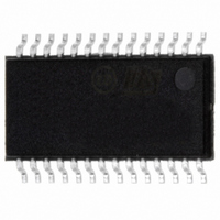
ST7540TR STMicroelectronics, ST7540TR Datasheet - Page 37

ST7540TR
Manufacturer Part Number
ST7540TR
Description
IC TXRX FSK POWER LINE 28-TSSOP
Manufacturer
STMicroelectronics
Type
Transceiverr
Datasheet
1.ST7540TR.pdf
(44 pages)
Specifications of ST7540TR
Number Of Drivers/receivers
1/1
Voltage - Supply
5 V ~ 9 V
Mounting Type
Surface Mount
Package / Case
28-TSSOP Exposed Pad, 28-eTSSOP, 28-HTSSOP
For Use With
497-5485 - BOARD EVAL ST7540 PWR LINE TXRX
Lead Free Status / RoHS Status
Lead free / RoHS Compliant
Protocol
-
Lead Free Status / Rohs Status
Compliant
Other names
497-5528-2
Available stocks
Company
Part Number
Manufacturer
Quantity
Price
Company:
Part Number:
ST7540TR
Manufacturer:
FENGHUA
Quantity:
400 000
Company:
Part Number:
ST7540TR
Manufacturer:
ST
Quantity:
2 100
Part Number:
ST7540TR
Manufacturer:
ST
Quantity:
20 000
ST7540
7.3
7.4
7.5
7.6
Reset & watchdog
RSTO Output is a reset generator for the application circuitry. During the ST7540 startup
sequence is forced low. RSTO becomes high after a T
startup sequence.
Inside ST7540 is also embedded a watchdog function. The watchdog function is used to
detect the occurrence of a software fault of the Host Controller. The watchdog circuitry
generates an internal and external reset (RSTO low for T
watchdog timer. The watchdog timer reset can be achieved applying a negative pulse on
WD pin (see
Figure 23. Reset and Watchdog Timing
Output clock
MCLK is the master clock output. The clock frequency sourced can be programmed through
the Control Register to be a ratio of the crystal oscillator frequency (Fosc, Fosc/2 Fosc/4).
The transition between one frequency and another is done only at the end of the ongoing
cycle. The oscillator can be disabled using Control Register bits 15 and 16
Output voltage level freeze
The Output Level Freeze function, when enabled, turns off the Voltage Control Loop once
the ALC stays in a stable condition for about 3 periods of control loop, and maintains a
constant gain until the end of transmission. Output Level Freeze can be enabled using
Control Register bit 17
Register (Control Register bit 21=”1”).
Extended control register
When Extended Control Register function is enabled, all the 48 bits of Control Register are
programmable. Otherwise, only the first 24 bits of Control Register are programmable. The
functions Header Recognition, Frame Bit Count and Output Voltage Freeze are available
only if Extended Control Register function is enabled. Extended Control Register can be
enabled using Control Register bit
RSTO
WD
Figure
T
RSTO
23).
(Table
12). This function is available only using the Extended Control
T
WD
21(Table
T
WM
12).
T
WO
Auxiliary analog and digital functions
RSTO
RSTO
delay from the end of oscillator
time) on expiry of the internal
T
RSTO
(Table
D03IN1410
12).
37/44


