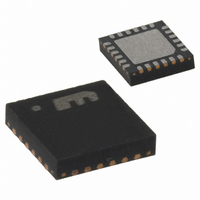
MIC3001GML Micrel Inc, MIC3001GML Datasheet - Page 70

MIC3001GML
Manufacturer Part Number
MIC3001GML
Description
IC FOM MANAGEMENT W/CALIBR 24MLF
Manufacturer
Micrel Inc
Type
Transceiverr
Datasheet
1.MIC3001GML.pdf
(76 pages)
Specifications of MIC3001GML
Protocol
SDHj Sonet
Voltage - Supply
3 V ~ 3.6 V
Mounting Type
Surface Mount
Package / Case
24-MLF®, QFN
Lead Free Status / RoHS Status
Lead free / RoHS Compliant
Number Of Drivers/receivers
-
Other names
576-1753-5
MIC3001GML
MIC3001GML
Available stocks
Company
Part Number
Manufacturer
Quantity
Price
Company:
Part Number:
MIC3001GML
Manufacturer:
Micrel Inc
Quantity:
1 801
Part Number:
MIC3001GMLTR
Manufacturer:
MICREL/麦瑞
Quantity:
20 000
Micrel, Inc.
Choosing C
The APC loop is compensated by a capacitor, C
connected from COMP to either V
adjusts the slew rate and bandwidth of the loop as follows:
where:
these relationships are shown graphically in Figure 28 and
Figure 29.
The loop response should be tailored to the data rate,
encoding format and maximum run-lengths, and required
laser turn-on time. Higher data rates and/or shorter
maximum run lengths and/or faster turn-on times call for
smaller capacitors. Lower data rates and/or longer maximum
run lengths and/or slower turn-on times call for larger
capacitors. In order to meet the SFP/GBIC turn-on
requirement of 1ms, for example, do not employ a capacitor
larger than 20nF. Low ESR capacitors such as ceramics will
give the best results. Excessive ESR will reduce the
effectiveness of C
exceed V
August 2004
I
G
SLEW
M
Figure 29. Open Loop Unity-Gain Bandwidth
DDA
= 125µMho
= 64µA,
Figure 28. Slew Rate vs. C
. Some typical values are shown in Table 22.
COMP
COMP
. The capacitor’s voltage rating must
vs. C
COMP
DDA
or GNDA. This capacitor
COMP
Value
COMP
,
70
While there is no theoretical upper limit on the size of
C
changes
compensation. The typical temperature compensation
update period is 1.6s. Therefore, a maximum size of 1mF
is recommended. If laser turn-on time is not a factor, a
value between 100nF and 1mF can be used for virtually
any typical application. The tradeoff is that higher value
capacitors have a larger physical size and cost.
In order to maximize the power supply rejection ratio
(PSRR), C
V
transistor (SRCE bit = 1). C
V
a PNP transistor (SRCE bit =0).
Measuring Laser Bias Current
VILD+ and VILD– form a pair of pseudo-differential A/D
inputs for measuring laser diode bias current via a sense
resistor. The signal applied to these inputs is converted to
a single-ended, ground-referenced signal for input into
the ADC and bias current fault comparator. These inputs
have limited common-mode voltage range. The full-scale
differential input range is V
Figure
implementation of this function. Note that VILD– is always
connected to the circuit’s reference potential: V
case of a common-anode transmitter optical sub-
assembly (TOSA) and GND in the case of a common-
cathode TOSA. Note that the monitor photodiode current
will also flow in the sense resistor. This will result in a
small offset in the measured bias current. The APC
function will hold this term constant, so it can be corrected
for in the external calibration constants. The sensing
resistor could also be connected between V
emitter of Q1 on figure 26 or between the emitter of Q1
and GND on Figure 27.
Interfacing To Laser Drivers
In order for the MIC3001 to control the modulation current
of the laser diode, an interface circuit may be required
depending on the method used by the driver to set its
modulation current level. Generally, most laser diode
driver ICs use one of three methods:
8b/10b encoding, ≥1Gbps, t
SONET (62
≥155Mbps, t
≥155Mbps
BIAS
DDA
COMP
a) A current, I
when the V
, it is desirable for the loop to be able to track the
output is sourcing current, e.g., driving an NPN
IC. The modulation current delivered by the driver
is then some fixed multiple of I
an example of this type of driver. A simple circuit
26
COMP
Table 22. Typical Values for C
b
resulting
/64
ON
and
Application
≤ 1ms
b
should be returned to GNDA when the
BIAS
encoding), ≥1Gbps
hbwhelp@micrel.com
SET
Figure
output is sinking current, e.g., driving
, is sourced into a pin on the driver
from
REF
ON
/4 or about 300mV.
27
COMP
≤ 1ms
periodic
illustrate
should be returned to
SET
or (408) 955-1690
M9999-082404-A
. The SY88912 is
COMP
C
temperature
the
DD
COMP
MIC3001
100
DD
10
22
22
and the
typical
(nF)
in the


