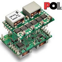
PMR8210P Ericsson Power Modules, PMR8210P Datasheet - Page 11

PMR8210P
Manufacturer Part Number
PMR8210P
Description
DC/DC Switching Controllers PoL Regul in 4.5-14V O/P 0.7-3.6 50A
Manufacturer
Ericsson Power Modules
Datasheet
1.PMR8210SR.pdf
(21 pages)
Specifications of PMR8210P
Number Of Outputs
1
Output Voltage
3 V to 5.25 V
Output Current
40 A
Output Power
132 W
Switching Frequency
600 KHz
Maximum Operating Temperature
+ 85 C
Minimum Operating Temperature
- 40 C
Lead Free Status / Rohs Status
Lead free / RoHS Compliant
resistor directly between pins 18 and 4, as close to the
regulator as possible, using dedicated PCB traces.
(2) Never connect capacitors from Vo Adjust to either +
Sense, GND, or Vo. Any capacitance added to the Vo Adjust
pin affects the stability of the regulator.
(3) For output voltages less than 1.2 V, the output ripple may
increase (up to 2 ) when operating at input voltages greater
than (Vo 12). Adjusting the switching frequency using the
SmartSync feature may increase or decrease this ratio.
Parallel Operation
The PMR 8210 module is capable of being configured in
parallel with another PMR 8210 module to share load current.
To parallel the two modules, it is necessary to configure one
module as the Master and one module as the Slave. To
configure a module as the Master, connect the CONFIG pin
(pin 1) to GND. The CONFIG pin of the Slave must be
connected to V I . In order to share current, pins 2 through 5 of
both the Master and Slave must be connected between the
two modules. The module that is configured as the MASTER
is used to control all of the functions of the two modules
including Inhibit, ON/OFF control, AutoTrack sequencing,
TurboTrans, SmartSync, +/- Remote Sense, and Output
Voltage Adjust.
The MASTER and the SLAVE must be powered from the
same input voltage supply.
When using TurboTrans while paralleling two modules, the
TurboTrans resistor, R TT , must be connected from the
TurboTrans pin (pin 19) of the Master module to the +Sense
pin (pin 17) of the Master module. When paralleling modules
the procedure to calculate the proper value of output
capacitance and R TT is similar to that explained in the
TurboTrans Selection section, however the values must be
calculated for a single module. Therefore, the total output
current load step must be halved before determining the
required output capacitance and the R TT value as explained
in the TurboTrans Selection section. The value of output
capacitance calculated is the minimum required output
capacitance per module and the value of RTT must be
calculated using this value of output capacitance. The
E
Prepared (also subject responsible if other)
ECOCOLO
Approved
SEC/D (Julia You)
PMR 8000 series PoL Regulator
Input 8 - 14 V, Output up to 40 A / 210 W
×
×
Checked
EJANLLI
Ericsson Internal
PRODUCT SPECIFICATION
No.
3/1301-BMR 629 8210 Uen
Date
2009-09-28
TurboTrans pin of the Slave module must be left open.
Current sharing layout
In current sharing applications the V I pins of both modules
must be connected to the same input bus. The V O pins of
both modules are connected together to power the load. The
GND pins of both modules are connected via the GND plane.
Four other inter-connection pins are connected between the
modules. Below figure shows the required layout of the inter-
connection pins for two modules configured to share current.
Notice that the Share (pin 2) connection is routed between the
Comp (pin 3) and CLKIO (pin 5) connections. AGND (pin 4)
should be connected as a thicker trace on an adjacent layer,
running parallel to pins 2, 3 and 5. AGND must not be
connected to the GND plane.
Remote Sense
The products have remote sense that can be used to
compensate for voltage drops between the output and the
point of load. The sense traces should be located close to the
PCB ground layer to reduce noise susceptibility. The remote
sense circuitry will compensate for up to 0.3 voltage drop
between output pins and the point of load.
If the remote sense is not needed +Sense should be
connected to +Out and –Sense should be connected to –Out.
Over Temperature Protection (OTP)
The regulators are protected from thermal overload by an
internal over temperature shutdown circuit. If the internal
temperature exceeds the OTP threshold, the module’s inhibit
control is internally pulled low. This turns the output off. The
voltage drops as the external output capacitors are discharged
by the load circuit. The product will make continuous attempts
to start up (non-latching mode) and resume normal operation
automatically when the temperature has dropped >10°C below
the temperature threshold.
Technical Specification
EN/LZT 146 411 R1B November 2009
© Ericsson AB
Rev
C
Reference
3 (9)
11


