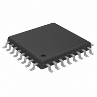
MAX3421EEHJ+T Maxim Integrated Products, MAX3421EEHJ+T Datasheet - Page 26

MAX3421EEHJ+T
Manufacturer Part Number
MAX3421EEHJ+T
Description
IC USB PERIPH/HOST CNTRL 32TQFP
Manufacturer
Maxim Integrated Products
Datasheet
1.MAX3421EETJ.pdf
(32 pages)
Specifications of MAX3421EEHJ+T
Controller Type
USB Peripheral Controller
Interface
USB/Serial
Voltage - Supply
3 V ~ 3.6 V
Current - Supply
15mA
Operating Temperature
-40°C ~ 85°C
Mounting Type
Surface Mount
Package / Case
32-TQFP, 32-VQFP
For Use With
MAX3421EVKIT-1+ - EVAL KIT FOR MAX3421E
Lead Free Status / RoHS Status
Lead free / RoHS Compliant
inputs, and the GPX pin is configured to serve as a sec-
ond MAX3421E interrupt pin that activates only when a
GPIN pin changes state. One of the eight GPOUT pins
turns the V
GPIN and GPOUT pins are available to the system.
The MAX3421E withstands V
on the USB connector side of the 33Ω series resistors.
D+, D-, and VBCOMP possess extra protection against
static electricity to protect the devices up to ±15kV. The
ESD structures withstand high ESD in all operating
modes: normal operation, suspend mode, and powered
down. VBCOMP and V
connected to ground as close to the pins as possible. D+,
D-, and VBCOMP provide protection to the following limits:
USB Peripheral/Host Controller
with SPI Interface
• ±15kV using the Human Body Model
• ±8kV using the Contact Discharge method specified
• ±12kV using the IEC 61000-4-2 Air-Gap Method
Figure 21. MAX3421E in a Host Application
26
in IEC 61000-4-2
______________________________________________________________________________________
"A" CONNECTOR
BUS
USB
switch on and off. Seven MAX3421E
Short-Circuit Protection
V
GND
BUS
CC
4.7μF
D+
D-
require 1µF ceramic capacitors
OUT
BUS
ESD Protection
33Ω
33Ω
shorts to D+ and D-
5V SWITCH WITH
AND OC DETECT
CURRENT LIMIT
D+
D-
VBCOMP
GPOUT
ON
FLAG
GPIN
IN
GND
MAX3421E
ESD performance depends on a variety of conditions.
Contact Maxim for a reliability report that documents
test setup, test methodology, and test results.
Figure 22 shows the Human Body Model, and Figure 23
shows the current waveform generated when dis-
charged into a low impedance. This model consists of
a 100pF capacitor charged to the ESD voltage of inter-
est, which then discharges into the test device through
a 1.5kΩ resistor.
The IEC 61000-4-2 standard covers ESD testing and
performance of finished equipment. It does not specifi-
cally refer to integrated circuits. The major difference
between tests done using the Human Body Model and
IEC 61000-4-2 is a higher peak current in IEC 61000-4-
2, due to lower series resistance. Hence, the ESD with-
stand voltage measured to IEC 61000-4-2 generally is
lower than that measured using the Human Body
Model. Figure 24 shows the IEC 61000-4-2 model. The
RES
C
XI
XI
12MHz
V
CC
XO
V
L
CERAMIC
C
XO
1.0μF
SCLK
MOSI
MISO
GPX
INT
SS
ESD Test Conditions
0.1μF
INT1
INT2
Human Body Model
REGULATOR
WITH POR
3.3V
GND
V
μP
5V
CC
IEC 61000-4-2


