DS2482X-101+T Maxim Integrated Products, DS2482X-101+T Datasheet - Page 9
DS2482X-101+T
Manufacturer Part Number
DS2482X-101+T
Description
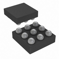
IC MASTER I2C-1WIRE 1CH 9-WLP
Manufacturer
Maxim Integrated Products
Datasheet
1.DS2482X-101T.pdf
(24 pages)
Specifications of DS2482X-101+T
Controller Type
I²C Bus Controller
Interface
I²C
Voltage - Supply
2.9 V ~ 5.5 V
Current - Supply
750µA
Operating Temperature
-40°C ~ 85°C
Mounting Type
Surface Mount
Package / Case
9-WLP
Lead Free Status / RoHS Status
Lead free / RoHS Compliant


The DS2482-101 understands eight function com-
mands that fall into four categories: device control, I
communication, 1-Wire setup, and 1-Wire communica-
tion. The feedback path to the host is controlled by a
read pointer, which is set automatically by each func-
tion command for the host to efficiently access relevant
information. The host processor sends these com-
mands and applicable parameters as strings of one or
two bytes using the I
requires that each byte be acknowledged by the
receiving party to confirm acceptance or not be
acknowledged to indicate an error condition (invalid
code or parameter) or to end the communication. See
the I
including acknowledge.
Command Code
Command Parameter
Description
Typical Use
Restriction
Error Response
Command Duration
1-Wire Activity
Read Pointer Position
Status Bits Affected
Configuration Bits Affected
Command Code
Command Parameter
Description
Typical Use
Restriction
Error Response
Command Duration
1-Wire Activity
Read Pointer Position
Status Bits Affected
Configuration Bits Affected
Single-Channel 1-Wire Master with Sleep Mode
2
C Interface section for details of the I
_______________________________________________________________________________________
Function Commands
2
C interface. The I
F0h
None
Performs a global reset of device state machine logic. Terminates any ongoing 1-Wire
communication.
Device initialization after power-up; reinitialization (reset) as desired.
None (can be executed at any time).
None
Maximum 525ns. Counted from falling SCL edge of the command code acknowledge bit.
Ends maximum 262.5ns after the falling SCL edge of the command code acknowledge bit.
Status Register (for busy polling).
RST set to 1; 1WB, PPD, SD, SBR, TSB, DIR set to 0.
1WS, APU, SPU set to 0.
E1h
Pointer Code (see Table 1)
Sets the read pointer to the specified register. Overwrites the read pointer position of any 1-Wire
communication command in progress.
To prepare reading the result from a 1-Wire Read Byte command; random read access of
registers.
None (can be executed at any time).
If the pointer code is not valid, the pointer code is not acknowledged and the command is
ignored.
None. The read pointer is updated on the rising SCL edge of the pointer code acknowledge bit.
Not affected.
As specified by the pointer code.
None
None
2
2
C protocol
C protocol
2
C
The function commands are as follows:
1) Device Reset
2) Set Read Pointer
3) Write Configuration
4) 1-Wire Reset
Table 1. Valid Pointer Codes
Status Register
Read Data Register
Configuration Register
REGISTER SELECTION
5) 1-Wire Single Bit
6) 1-Wire Write Byte
7) 1-Wire Read Byte
8) 1-Wire Triplet
Set Read Pointer
Device Reset
CODE
C3h
E1h
F0h
9
Related parts for DS2482X-101+T
Image
Part Number
Description
Manufacturer
Datasheet
Request
R

Part Number:
Description:
WLP/I°/SINGLE-CH 1-W LN DR LF UCSP PARTIAL
Manufacturer:
Maxim Integrated Products
Part Number:
Description:
WLP 8/I°/Single-Channel 1-Wire® Master with Sleep Mode
Manufacturer:
Maxim Integrated Products

Part Number:
Description:
IC MASTER I2C-1WIRE 1CH 9-WLP
Manufacturer:
Maxim Integrated Products
Datasheet:
Part Number:
Description:
MAX7528KCWPMaxim Integrated Products [CMOS Dual 8-Bit Buffered Multiplying DACs]
Manufacturer:
Maxim Integrated Products
Datasheet:
Part Number:
Description:
Single +5V, fully integrated, 1.25Gbps laser diode driver.
Manufacturer:
Maxim Integrated Products
Datasheet:
Part Number:
Description:
Single +5V, fully integrated, 155Mbps laser diode driver.
Manufacturer:
Maxim Integrated Products
Datasheet:
Part Number:
Description:
VRD11/VRD10, K8 Rev F 2/3/4-Phase PWM Controllers with Integrated Dual MOSFET Drivers
Manufacturer:
Maxim Integrated Products
Datasheet:
Part Number:
Description:
Highly Integrated Level 2 SMBus Battery Chargers
Manufacturer:
Maxim Integrated Products
Datasheet:
Part Number:
Description:
Current Monitor and Accumulator with Integrated Sense Resistor; ; Temperature Range: -40°C to +85°C
Manufacturer:
Maxim Integrated Products
Part Number:
Description:
TSSOP 14/A°/RS-485 Transceivers with Integrated 100O/120O Termination Resis
Manufacturer:
Maxim Integrated Products
Part Number:
Description:
TSSOP 14/A°/RS-485 Transceivers with Integrated 100O/120O Termination Resis
Manufacturer:
Maxim Integrated Products
Part Number:
Description:
QFN 16/A°/AC-DC and DC-DC Peak-Current-Mode Converters with Integrated Step
Manufacturer:
Maxim Integrated Products
Part Number:
Description:
TDFN/A/65V, 1A, 600KHZ, SYNCHRONOUS STEP-DOWN REGULATOR WITH INTEGRATED SWI
Manufacturer:
Maxim Integrated Products
Part Number:
Description:
Integrated Temperature Controller f
Manufacturer:
Maxim Integrated Products
Part Number:
Description:
SOT23-6/I°/45MHz to 650MHz, Integrated IF VCOs with Differential Output
Manufacturer:
Maxim Integrated Products