DS2482X-101+T Maxim Integrated Products, DS2482X-101+T Datasheet
DS2482X-101+T
Specifications of DS2482X-101+T


Related parts for DS2482X-101+T


DS2482X-101+T Summary of contents
Page 1
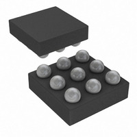
... MOSFET for Stronger Pullup Requirements ♦ Supports Power-Saving Sleep Mode 2 C slave ♦ One Address Input for I ♦ Operating Range: 2.9V to 5.5V, -40°C to +85°C ♦ 9-Bump WLP Package Applications PART DS2482X-101+T + Denotes a lead(Pb)-free/RoHS-compliant package Tape and reel SDA SCL PCTLZ ...
Page 2
Single-Channel 1-Wire Master with Sleep Mode ABSOLUTE MAXIMUM RATINGS Voltage Range on Any Pin Relative to Ground.........-0.5V to +6V Maximum Current into Any Pin..........................................±20mA Operating Temperature Range ...........................-40°C to +85°C Stresses beyond those listed under “Absolute Maximum Ratings” may cause ...
Page 3
Single-Channel 1-Wire Master with Sleep Mode ELECTRICAL CHARACTERISTICS (continued 2.9V to 5.5V -40°C to +85°C PARAMETER SYMBOL Write-Zero Low Time Write-Zero Recovery Time t Reset Low Time Presence-Detect Sample Time Sampling for Short and ...
Page 4
Single-Channel 1-Wire Master with Sleep Mode ELECTRICAL CHARACTERISTICS (continued 2.9V to 5.5V -40°C to +85°C PARAMETER SYMBOL Input Current Each Input/Output Pin with an Input Voltage Between 0 and CC(MAX) 0.9 x ...
Page 5
Single-Channel 1-Wire Master with Sleep Mode PIN NAME Active-Low Control Output for an External p-Channel MOSFET. Provides extra power to the 1-Wire line, e.g., A1 PCTLZ for use with 1-Wire devices that require a higher current temporarily to operate. A2 ...
Page 6
Single-Channel 1-Wire Master with Sleep Mode Device Registers The DS2482-101 has three registers that the I can read: Configuration, Status, and Read Data. These registers are addressed by a read pointer. The position of the read pointer, i.e., the register ...
Page 7
Single-Channel 1-Wire Master with Sleep Mode Strong Pullup (SPU) The SPU bit is used to activate the strong pullup func- tion prior to a 1-Wire Write Byte or 1-Wire Single Bit command. Strong pullup is commonly used with 1-Wire EEPROM ...
Page 8
Single-Channel 1-Wire Master with Sleep Mode BIT 7 BIT 6 BIT 5 DIR TSB The read-only Status Register is the general means for the DS2482-101 to report bit-type data from the 1-Wire side, 1-Wire busy status, and its own reset ...
Page 9
Single-Channel 1-Wire Master with Sleep Mode Function Commands The DS2482-101 understands eight function com- mands that fall into four categories: device control, I communication, 1-Wire setup, and 1-Wire communica- tion. The feedback path to the host is controlled by a ...
Page 10
Single-Channel 1-Wire Master with Sleep Mode D2h Command Code Command Parameter Configuration Byte Writes a new configuration byte. The new settings take effect immediately. Note: When writing to Description the Configuration Register, the new data is accepted only if the ...
Page 11
Single-Channel 1-Wire Master with Sleep Mode Command Code 87h Command Parameter Bit Byte Generates a single 1-Wire time slot with a bit value “V” as specified by the bit byte at the 1-Wire line (see Table 2 value ...
Page 12
Single-Channel 1-Wire Master with Sleep Mode t MSR IH1 V IL1 PULLUP (SEE FIGURE 2) Figure 5. Write-Zero Time Slot t W1L IH1 V IL1 PULLUP (SEE FIGURE ...
Page 13
Single-Channel 1-Wire Master with Sleep Mode Command Code A5h Command Parameter Data Byte Description Writes a single data byte to the 1-Wire line. To write commands or data to the 1-Wire line. Equivalent to executing eight 1-Wire Single Bit Typical ...
Page 14
Single-Channel 1-Wire Master with Sleep Mode Command Code 78h Command Parameter Direction Byte Generates three time slots: two read time slots and one write time slot at the 1-Wire line. The type of write time slot depends on the result ...
Page 15
Single-Channel 1-Wire Master with Sleep Mode MSB FIRST SDA SLAVE R/W ADDRESS SCL 1–7 8 IDLE START CONDITION 2 Figure Protocol Overview General Characteristics 2 The I C bus uses a data line (SDA) plus a clock ...
Page 16
Single-Channel 1-Wire Master with Sleep Mode SDA t BUF t LOW SCL t t HD:STA R STOP START NOTE: TIMING IS REFERENCED TO V AND V . IL(MAX) IH(MIN) 2 Figure Timing Diagram The following terminology is ...
Page 17
Single-Channel 1-Wire Master with Sleep Mode slave address. However, some time later the slave may refuse to accept data, possibly because of an invalid command code or parameter. In this case, the slave device does not acknowledge any of the ...
Page 18
Single-Channel 1-Wire Master with Sleep Mode Device Reset (After Power-Up) S AD,0 A DRST A Activities that are underlined denote an optional read access to verify the success of the command. Set Read Pointer (To Read from Another Register) Case ...
Page 19
Single-Channel 1-Wire Master with Sleep Mode 1-Wire Single Bit (To Generate a Single Time Slot on the 1-Wire Line) Case A: 1-Wire Idle (1WB = 0), No Busy Polling S AD,0 A 1WSB A The idle time is needed for ...
Page 20
Single-Channel 1-Wire Master with Sleep Mode 1-Wire Read Byte (To Read a Byte from the 1-Wire Line) Case A: 1-Wire Idle (1WB = 0), No Busy Polling, Set Read Pointer After Idle Time S AD,0 A 1WRB A S AD,0 ...
Page 21
Single-Channel 1-Wire Master with Sleep Mode 1-Wire Triplet (To Perform a Search ROM Function on the 1-Wire Line) (continued) Case B: 1-Wire Idle (1WB = 0), Busy Polling Until the 1-Wire Command is Completed S AD,0 A 1WT A When ...
Page 22
Single-Channel 1-Wire Master with Sleep Mode Applications Information SDA and SCL Pullup Resistors SDA is an open-drain output on the DS2482-101 that requires a pullup resistor to realize high-logic levels. Because the DS2482-101 uses SCL only as input (no clock ...
Page 23
Single-Channel 1-Wire Master with Sleep Mode TOP VIEW (BUMP SIDE DOWN) DS2482-101 PCTLZ B SCL C For the latest package outline information and land patterns www.maxim-ic.com/packages. Note that a “+”, “#”, or “-” in the ...
Page 24
... Maxim cannot assume responsibility for use of any circuitry other than circuitry entirely embodied in a Maxim product. No circuit patent licenses are implied. Maxim reserves the right to change the circuitry and specifications without notice at any time. 24 ____________________Maxim Integrated Products, 120 San Gabriel Drive, Sunnyvale, CA 94086 408-737-7600 © 2010 Maxim Integrated Products DESCRIPTION Maxim is a registered trademark of Maxim Integrated Products, Inc ...