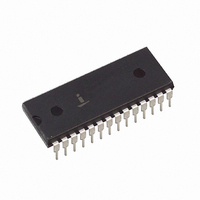
CP82C59AZ Intersil, CP82C59AZ Datasheet - Page 18

CP82C59AZ
Manufacturer Part Number
CP82C59AZ
Description
IC INTERFACE 5V 8MHZ 28-DIP
Manufacturer
Intersil
Datasheet
1.CS82C59AZ.pdf
(22 pages)
Specifications of CP82C59AZ
Controller Type
CMOS Priority Interrupt Controller
Voltage - Supply
4.5 V ~ 5.5 V
Current - Supply
1mA
Operating Temperature
0°C ~ 70°C
Mounting Type
Through Hole
Package / Case
28-DIP (0.600", 15.24mm)
Supply Voltage Range
4.5V To 5.5V
Supply Current
1mA
Digital Ic Case Style
DIP
No. Of Pins
28
Operating Temperature Range
0°C To +70°C
Filter Terminals
Through Hole
Rohs Compliant
Yes
Lead Free Status / RoHS Status
Lead free / RoHS Compliant
Interface
-
Lead Free Status / Rohs Status
RoHS Compliant part
Electrostatic Device
Available stocks
Company
Part Number
Manufacturer
Quantity
Price
Part Number:
CP82C59AZ
Manufacturer:
INTERSIL
Quantity:
20 000
AC Electrical Specifications
NOTE:
AC Test Circuit
NOTE: Includes stray and jig capacitance.
TIMING RESPONSES
1. Worst case timing for TCHCL in an actual microprocessor system is typically greater than the values specified for the 82C59A,
(12) TWHWL
(10) TCVlAL
(15) TRHDZ
(17) TlALCV
(19) TRHEH
(21) TCVDV
(11) TRHRL
(13) TCHCL
(14) TRLDV
(20) TAHDV
(5) TWHAX
(6) TWLWH
(7) TDVWH
(8) TWHDX
(18) TRLEL
(4) TAHWL
(16) TJHlH
(9) TJLJH
SYMBOL
(i.e. 8085A = 1.6µs, 8085A -2 = 1µs, 80C86 = 1µs, 80C286 -10 = 131ns, 80C286 -12 = 98ns).
(Note 1)
A0/CS Setup to WR
A0/CS Hold after WR
WR Pulse Width
Data Setup to WR
Data Hold after WR
Interrupt Request Width Low
Cascade Setup to Second or Third INTA (Slave
Only)
End of RD to next RD, End of INTA (within an
INTA sequence only)
End of WR to next WR
End of Command to next command (not same
command type), End of INTA
sequence to next INTA sequence
Data Valid from RD/INTA
Data Float after RD/INTA
Interrupt Output Delay
Cascade Valid from First INTA
(Master Only)
Enable Active from RD or INTA
Enable Inactive from RD or INTA
Data Valid from Stable Address
Cascade Valid to Valid Data
18
PARAMETER
V
DEVICE UNDER
OUTPUT FROM
CC
CONDITION
= +5.0V ±10%, GND = 0V, T
TEST
1
2
TEST
TEST CONDITION DEFINITION TABLE
1.7V
V
V
CC
1
C
(NOTE)
82C59A
82C59A
1
MIN
165
240
100
160
190
500
55
0
5
5
5
-
-
-
-
-
-
-
5MHz
A
1.8kΩ
523Ω
= Operating Temperature Range (Continued)
R
1
MAX
V
160
100
350
565
125
210
300
60
1
-
-
-
-
-
-
-
-
-
-
R
R
1
2
1.8kΩ
Open
MIN
160
100
160
190
400
95
40
R
0
5
5
5
-
-
-
-
-
-
-
2
8MHz
TEST
POINT
MAX
120
300
360
100
200
200
85
50
-
-
-
-
-
-
-
-
-
-
100pF
50pF
C
1
MIN
40
60
70
30
90
60
90
0
0
0
5
12.5MHz
-
-
-
-
-
-
-
MAX
40
22
90
50
40
22
60
70
-
-
-
-
-
-
-
-
-
-
UNITS
ns
ns
ns
ns
ns
ns
ns
ns
ns
ns
ns
ns
ns
ns
ns
ns
ns
ns
CONDITIONS
March 17, 2006
TEST
1
2
1
1
1
1
1
1
FN2784.5


