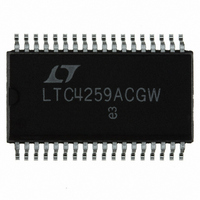
LTC4259ACGW#PBF Linear Technology, LTC4259ACGW#PBF Datasheet - Page 22

LTC4259ACGW#PBF
Manufacturer Part Number
LTC4259ACGW#PBF
Description
IC CTRLR POE QUAD AC DISC 36SSOP
Manufacturer
Linear Technology
Datasheet
1.LTC4259ACGW.pdf
(32 pages)
Specifications of LTC4259ACGW#PBF
Controller Type
Power over Ethernet Controller (POE)
Interface
I²C
Voltage - Supply
3 V ~ 4 V
Current - Supply
2.5mA
Operating Temperature
0°C ~ 70°C
Mounting Type
Surface Mount
Package / Case
36-SSOP
Lead Free Status / RoHS Status
Lead free / RoHS Compliant
Available stocks
Company
Part Number
Manufacturer
Quantity
Price
APPLICATIO S I FOR ATIO
LTC4259A
values of C
LTC Applications department for additional support.
When choosing C
derating of the capacitors. Capacitors built around an X7R
dielectric will have about 60% of the specified capacitance
at their rated voltage. Operated at half their rated voltage,
X7R capacitors exhibit more than 80% of their specified
capacitance. With other ceramic dielectrics commonly
used in 50V and 100V chip capacitors, capacitance falls
much more dramatically with voltage. At their rated volt-
age, Y5V or Z5U capacitors exhibit less than 30% of their
zero-bias capacitance. Ceramic capacitors can also have
significantly less capacitance at elevated temperatures. In
order to produce the desired capacitance at the operating
bias, 100V or 250V X7R capacitors should be used with
the LTC4259A.
As illustrated in Figure 19, the Power over Ethernet con-
nection between the PSE and PD includes a large amount
of capacitance. Cable capacitance is particularly troubling
because CAT-3 and CAT-5 pair-to-pair capacitance is not
22
DET
OSCILLATOR
CURRENT
, R
SENSE
INPUT
DET
DET
U
and C
–48V
GND
and C
U
PSE
LTC4259A
PSE
Figure 18. AC Disconnect Single Port Application Circuit (Port 4 Shown)
Figure 19. Simplified AC Disconnect Circuit with Impedances at 100Hz
~16k
1/4
~7k
is discouraged. Contact the
V
, carefully consider voltage
EE
0.5Ω 1%
OSCIN
R
LEVEL
SHIFT
S4
W
SENSE4
R
1k
DET
C
0.47µF
C
0.10µF
DET
PSE
GATE4
DGND
Q4
Z
Z
CABLE
LINK
DETECT4
U
AGND
OUT4
< 14k
< 32k
R
10k
D
S1B
OUT4
AC4
D
CMPD3003
DET4
C
CABLE
tightly specified by the IEEE 802.3 standard or well con-
trolled by cable manufacturers. Considering that patch
panels, additional connectors, old wiring, etc. are likely to
be placed between the PSE and PD, pair-to-pair capaci-
tance is a pretty nebulous quantity. Consequently, the
cable’s contribution to the port impedance (at the fre-
quency used for AC disconnect) can be a concern.
Assumimg that f
0.05µF of cable capacitance gives a port impedance of 10k
at 100Hz. The PD AC signature resistance is about 25k.
Connecting a PD with the maximum allowed resistance of
26.25k brings the connection impedance to about 8k. The
presence of a PD only makes a 20% reduction in the port
impedance requiring the AC disconnect circuitry to be
quite sensitive. When the OSCIN pin is driven with a sine
wave, the LTC4259A is able to distinguish between capaci-
tive impedance and resistive impedance on the Power over
Ethernet connection. AC disconnect is reliable for cable
capacitance up to about 0.2µF, nearly an order of magni-
tude greater than worst case for a long CAT-3 or CAT-5
cable.
≤ 0.05µF
100V X7R
R
1k
DET4
C
0.47µF
100V X7R
C
DET4
0.1µF
<32k
PSE4
Z
PD
< 14k
OSCIN
C
PD_D
R
≤26.25k
PD_D
is 100Hz, the 0.1µF of C
≥ 0.05µF
PD
PD
C
≥0.05µF
PD_D
4259A F18
R
4259A F19
PD_D
< 26.25k
PSE
4259afb
plus


