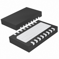
LTC4267CDHC-3#PBF Linear Technology, LTC4267CDHC-3#PBF Datasheet - Page 12

LTC4267CDHC-3#PBF
Manufacturer Part Number
LTC4267CDHC-3#PBF
Description
IC POE 802.3AF W/REG 16-DFN
Manufacturer
Linear Technology
Datasheet
1.LTC4267CGN-3PBF.pdf
(32 pages)
Specifications of LTC4267CDHC-3#PBF
Controller Type
Power over Ethernet Controller (POE)
Interface
IEEE 802.3af
Current - Supply
3mA
Operating Temperature
0°C ~ 70°C
Mounting Type
Surface Mount
Package / Case
16-DFN
Lead Free Status / RoHS Status
Lead free / RoHS Compliant
Voltage - Supply
-
Available stocks
Company
Part Number
Manufacturer
Quantity
Price
LTC4267-3
APPLICATIO S I FOR ATIO
12
Classifi cation
Once the PSE has detected a PD, the PSE may option-
ally classify the PD. Classifi cation provides a method for
more effi cient allocation of power by allowing the PSE
to identify lower power PDs and allocate less power for
these devices. The IEEE 802.3af specifi cation defi nes fi ve
classes (Table 2) with varying power levels. The designer
selects the appropriate classifi cation based on the power
consumption of the PD. For each class, there is an as-
sociated load current that the PD asserts onto the line
during classifi cation probing. The PSE measures the PD
load current to determine the proper classifi cation and
PD power requirements.
During classifi cation (Figure 4), the PSE presents a fi xed
voltage between –15.5V and –20.5V to the PD. With the
input voltage in this range, the LTC4267-3 asserts a load
current from the V
The magnitude of the load current is set by the R
resistor. The resistor values associated with each class are
shown in Table 2. Note that the switching regulator will
not interfere with the classifi cation measurement since
the LTC4267-3 has not passed power to the regulator.
Table 2. Summary of IEEE 802.3af Power Classifi cations and
LTC4267-3 R
*Class 4 is currently reserved and should not be used.
Class
0
1
2
3
4
PSE
TO
Reserved
Optional
Optional
Optional
Figure 3. 25k Signature Resistor with Disable
Default
Usage
CLASS
V
LTC4267-3
25k SIGNATURE
PORTN
RESISTOR
Resistor Selection
at Input of PD
PORTP
Power Levels
0.44 to 12.95
6.49 to 12.95
0.44 to 3.84
3.84 to 6.49
U
Reserved*
Maximum
(W)
pin through the R
U
9k
16k
SIGNATURE DISABLE
Classifi cation
Load Current
Nominal
W
(mA)
10.5
18.5
<5
28
40
SIGDISA
V
PORTP
CLASS
U
42673 F03
LTC4267-3
Resistor
(Ω, 1%)
resistor.
R
Open
68.1
45.3
30.9
CLASS
124
CLASS
The IEEE 802.3af specifi cation limits the classifi cation
time to 75ms because a signifi cant amount of power is
dissipated in the PD. The LTC4267-3 is designed to handle
the power dissipation for this time period. If the PSE prob-
ing exceeds 75ms, the LTC4267-3 may overheat. In this
situation, the thermal protection circuit will engage and
disable the classifi cation current source in order to protect
the part. The LTC4267-3 stays in classifi cation mode until
the input voltage rises above the UVLO turn-on voltage.
V
The IEEE specifi cation dictates a maximum turn-on voltage
of 42V and a minimum turn-off voltage of 30V for the PD.
In addition, the PD must maintain large on-off hysteresis to
prevent resistive losses in the wiring between the PSE and
the PD from causing start-up oscillation. The LTC4267-3
incorporates an undervoltage lockout (UVLO) circuit that
monitors the line voltage at V
to apply power to the integrated switching regulator
(Figure 5). Before the power is applied to the switching
regulator, the P
the ground potential since there is no charge on capacitor
C1. When the input voltage rises above the UVLO turn-on
threshold, the LTC4267-3 removes the detection and clas-
sifi cation loads and turns on the internal power MOSFET.
C1 charges up under the LTC4267-3 current limit control
and the P
sequence is shown in Figure 1. The LTC4267-3 includes
a hysteretic UVLO circuit on V
applied to the load until the input voltage falls below the
UVLO turn-off threshold. Once the input voltage drops
below –30V, the internal power MOSFET is turned off and
–15.5V TO –20.5V
PORTN
PROBING
VOLTAGE
SOURCE
Undervoltage Lockout
Figure 4. IEEE 802.3af Classifi cation Probing
PSE
PSE CURRENT MONITOR
OUT
pin transitions from 0V to V
OUT
PSE
V
pin is high impedance and sitting at
CURRENT PATH
R
CLASS
PORTN
PORTN
R
V
LTC4267-3
CLASS
PORTN
PD
to determine when
that keeps power
V
PORTP
42673 F04
PORTN
CONSTANT
LOAD
CURRENT
INTERNAL
TO LTC4267-3
. This
42673f


