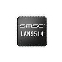
LAN9512-JZX SMSC, LAN9512-JZX Datasheet - Page 30

LAN9512-JZX
Manufacturer Part Number
LAN9512-JZX
Description
IC USB 2.0 ETHER CTRLR 64QFN
Manufacturer
SMSC
Specifications of LAN9512-JZX
Controller Type
Ethernet Controller
Interface
IEEE 802.3
Voltage - Supply
3 V ~ 3.6 V
Current - Supply
231mA
Operating Temperature
0°C ~ 70°C
Mounting Type
Surface Mount
Package / Case
64-QFN
Product
Ethernet Controllers
Standard Supported
802.3, 802.3u
Data Rate
1.5 Mbps to 480 Mbps
Supply Voltage (max)
3.6 V
Supply Voltage (min)
3 V
Supply Current (max)
231 mA
Maximum Operating Temperature
+ 70 C
Ethernet Connection Type
10/100 Base-T
Maximum Power Dissipation
763 mW
Minimum Operating Temperature
0 C
Mounting Style
SMD/SMT
For Use With
638-1093 - EVALUATION BOARD FOR LAN9512
Lead Free Status / Rohs Status
Lead free / RoHS Compliant
Other names
638-1086
Available stocks
Company
Part Number
Manufacturer
Quantity
Price
Company:
Part Number:
LAN9512-JZX
Manufacturer:
SMSC
Quantity:
5 510
Part Number:
LAN9512-JZX
Manufacturer:
SMSC
Quantity:
20 000
Revision 1.0 (11-24-09)
BITS
BITS
BITS
5:4
7:4
2:0
7:2
1:0
7:6
3
RESERVED
Port Re-Mapping Enable (PRTMAP_EN)
Selects the method used by the Hub to assign port numbers and disable
ports.
0 = Standard Mode. The following EEPROM addresses are used to define
which ports are enabled. The ports mapped as Port’n’ on the Hub are
reported as Port’n’ to the host, unless one of the ports is disabled, then the
higher numbered ports are remapped in order to report contiguous port
numbers to the host.
EEPROM Address 2Ah: Port Disable for Self-Powered operation
EEPROM Address 2Bh: Port Disable for Bus-Powered operation
1 = Port Re-Map mode. The mode enables remapping via the following
EEPROM addresses:
EEPROM Address 36h: Port Remap 12
EEPROM Address 37h: Port Remap 3
RESERVED
RESERVED
Upstream USB Electrical Signaling Drive Strength Boost Bit for
Upstream Port A (BOOST_IOUT_A)
00 = Normal electrical drive strength
01 = Elevated electrical drive strength (+4% boost)
10 = Elevated electrical drive strength (+8% boost)
11 = Elevated electrical drive strength (+12% boost)
RESERVED
Upstream USB Electrical Signaling Drive Strength Boost Bit for
Downstream Port 3 (BOOST_IOUT_3)
00 = Normal electrical drive strength
01 = Elevated electrical drive strength (+4% boost)
10 = Elevated electrical drive strength (+8% boost)
11 = Elevated electrical drive strength (+12% boost)
Table 3.6 Config Data Byte 3 Register (CFG3) Format
Table 3.7 Boost_Up Register (BOOSTUP) Format
Table 3.8 Boost_3:2 Register (BOOST32) Format
DESCRIPTION
DESCRIPTION
DESCRIPTION
DATASHEET
30
USB 2.0 Hub and 10/100 Ethernet Controller
SMSC LAN9512/LAN9512i
DEFAULT
DEFAULT
DEFAULT
000000b
000b
00b
00b
00b
0h
0b
Datasheet


