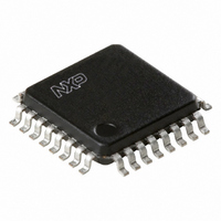
TDA8029HL/C206,118 NXP Semiconductors, TDA8029HL/C206,118 Datasheet - Page 34

TDA8029HL/C206,118
Manufacturer Part Number
TDA8029HL/C206,118
Description
IC SMART CARD READER 32-LQFP
Manufacturer
NXP Semiconductors
Datasheet
1.TDA8029HLC207118.pdf
(59 pages)
Specifications of TDA8029HL/C206,118
Controller Type
Smart Card Reader Interface
Interface
Serial
Voltage - Supply
2.7 V ~ 6 V
Current - Supply
250mA
Operating Temperature
-40°C ~ 90°C
Mounting Type
Surface Mount
Package / Case
32-LQFP
Lead Free Status / RoHS Status
Lead free / RoHS Compliant
Other names
568-3524-2
935273235118
TDA8029HL06BD-T
935273235118
TDA8029HL06BD-T
Available stocks
Company
Part Number
Manufacturer
Quantity
Price
Company:
Part Number:
TDA8029HL/C206,118
Manufacturer:
NXP Semiconductors
Quantity:
10 000
Philips Semiconductors
Table 54:
Table 55:
9397 750 14145
Product data sheet
Bit
7
6 to 4
3
2 to 0
Bit
Symbol
Reset
Access
FCR - FIFO control register (address Ch) bit allocation
FCR - FIFO control register (address Ch) bit description
8.10.2.4 FIFO control register (FCR)
8.10.2.5 UART status register (USR)
Symbol
-
PEC[2:0]
-
FL[2:0]
7
-
-
The UART Status Register (USR) is used by the microcontroller to monitor the activity of
the ISO UART and that of the time-out counter. If any of the status bits FER, OVR, PE,
EA, TO1, TO2 or TO3 are set, then signal INT0_N = LOW. The bit having caused the
interrupt is reset 2 s after the rising edge of signal RD during a read operation of register
USR.
If bit TBE/RBF is set and if the mask bit DISTBE/RBF within register UCR2 is not set, then
also signal INT0_N = LOW. Bit TBE/RBF is reset three clock cycles after data has been
written in register UTR, or three clock cycles after data has been read from register URR,
or when changing from transmission mode to reception mode.
If LCT mode is used for transmitting the last character, then bit TBE is not set at the end of
the transmission.
PEC2
6
0
Description
Not used.
Parity Error Counter. These bits determine the number of parity errors before setting bit
PE in register USR and pulling INT0_N LOW. PEC[2:0] = 000 means that if only one
parity error has occurred, bit PE is set; PEC[2:0] = 111 means that bit PE will be set
after 8 parity errors.
In protocol T = 0:
In protocol T = 1:
Not used.
FIFO Length. These bits determine the depth of the FIFO: FL[2:0] = 000 means length 1,
FL[2:0] = 111 means length 8.
•
•
•
•
•
If a correct character is received before the programmed error number is reached,
the error counter will be reset
If the programmed number of allowed parity errors is reached, bit PE in register USR
will be set as long as the USR has not been read
If a transmitted character is NAKed by the card, then the TDA8029 will automatically
retransmit it a number of times equal to the value programmed in PEC[2:0]. The
character will be resent at 15 ETU.
In transmission mode, if PEC[2:0] = 000, then the automatic retransmission is
invalidated. The character manually rewritten in register UTR will start at 13.5 ETU.
The error counter has no action (bit PE is set at the first wrong received character).
PEC1
5
0
Rev. 03 — 22 February 2005
PEC0
4
0
write
3
-
-
FL2
Low power single card reader
2
0
© Koninklijke Philips Electronics N.V. 2005. All rights reserved.
FL1
1
0
TDA8029
FL0
0
0
34 of 59


