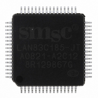
LAN83C185-JT SMSC, LAN83C185-JT Datasheet - Page 11

LAN83C185-JT
Manufacturer Part Number
LAN83C185-JT
Description
IC PHY 10/100 3.3V LP 64-TQFP
Manufacturer
SMSC
Datasheet
1.LAN83C185-JT.pdf
(60 pages)
Specifications of LAN83C185-JT
Controller Type
Ethernet Controller
Interface
MII
Voltage - Supply
3 V ~ 3.6 V
Current - Supply
40mA
Operating Temperature
0°C ~ 70°C
Mounting Type
Surface Mount
Package / Case
64-TQFP, 64-VQFP
Supply Voltage Range
2.97V To 3.63V
Digital Ic Case Style
TQFP
No. Of Pins
64
Operating Temperature Range
0°C To +70°C
Data Rate Max
100Mbps
Supply Voltage Max
3.6V
Rohs Compliant
Yes
Lead Free Status / RoHS Status
Lead free / RoHS Compliant
Other names
638-1009
Available stocks
Company
Part Number
Manufacturer
Quantity
Price
Company:
Part Number:
LAN83C185-JT
Manufacturer:
Standard
Quantity:
2 077
Company:
Part Number:
LAN83C185-JT
Manufacturer:
ALTERA
Quantity:
513
Company:
Part Number:
LAN83C185-JT
Manufacturer:
Microchip Technology
Quantity:
10 000
High Performance Single Chip Low Power 10/100 Ethernet Physical Layer Transceiver (PHY)
Datasheet
Chapter 3 Pin Description
SMSC LAN83C185
3.1
PIN NO.
41
42
39
35
47
32
31
44
45
I/O Signals
TXD0
TXD1
TX_EN
RX_ER
(RXD4)
COL
RXD0
RXD1
TXD2
TXD3
This chapter describes in detail the functionality of each of the five main architectural blocks.
The term “block” defines a stand-alone entity on the floor plan of the chip.
I
O
AI
AO
AI/O – Input or Output. Analog levels.
Note: Reset as used in the signal descriptions is defined as nRST being active low.
Configuration inputs are listed in parenthesis.
– Input. Digital TTL levels.
– Output. Digital TTL levels.
– Input. Analog levels.
– Output. Analog levels.
SIGNAL NAME
I
I
I
O
O
O
O
O
I
I
Table 3.1 MII Signals
TYPE
DATASHEET
Transmit Data 0: Bit 0 of the 4 data bits that are accepted
by the PHY for transmission.
Transmit Data 1: Bit 1 of the 4 data bits that are accepted
by the PHY for transmission.
Transmit Enable: Indicates that valid data is presented
on the TXD[3:0] signals, for transmission.
Receive Error: Asserted to indicate that an error was
detected somewhere in the frame presently being
transferred from the PHY.
In Symbol Interface (5B Decoding) mode, this signal is the
MII Receive Data 4: the MSB of the received 5-bit symbol
code-group.
MII Collision Detect: Asserted to indicate detection of
collision condition.
Receive Data 0: Bit 0 of the 4 data bits that are sent by
the PHY in the receive path.
Receive Data 1: Bit 1 of the 4 data bits that are sent by
the PHY in the receive path.
Transmit Data 2: Bit 2 of the 4 data bits that are accepted
by the PHY for transmission.
Transmit Data 3: Bit 3 of the 4 data bits that are accepted
by the PHY for transmission.
11
DESCRIPTION
Revision 0.8 (06-12-08)


