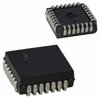
CS82C59AZ Intersil, CS82C59AZ Datasheet - Page 15

CS82C59AZ
Manufacturer Part Number
CS82C59AZ
Description
IC INTERRUPT CONTROLLER 28-PLCC
Manufacturer
Intersil
Datasheet
1.CS82C59AZ.pdf
(22 pages)
Specifications of CS82C59AZ
Controller Type
CMOS Priority Interrupt Controller
Interface
System Bus
Voltage - Supply
4.5 V ~ 5.5 V
Current - Supply
1mA
Operating Temperature
0°C ~ 70°C
Mounting Type
Surface Mount
Package / Case
28-PLCC
Lead Free Status / RoHS Status
Lead free / RoHS Compliant
Available stocks
Company
Part Number
Manufacturer
Quantity
Price
Company:
Part Number:
CS82C59AZ
Manufacturer:
Intersil
Quantity:
97
Company:
Part Number:
CS82C59AZ
Manufacturer:
Intersil
Quantity:
2 430
Company:
Part Number:
CS82C59AZ96
Manufacturer:
Melexis
Quantity:
14 042
Reading the 82C59A Status
The input status of several internal registers can be read to
update the user information on the system. The following
registers can be read via OCW3 (lRR and ISR) or OCW1
(lMR).
Interrupt Request Register (IRR): 8-bit register which
contains the levels requesting an interrupt to be
acknowledged. The highest request level is reset from the
lRR when an interrupt is acknowledged. lRR is not affected
by lMR.
In-Service Register (ISR): 8-bit register which contains the
priority levels that are being serviced. The ISR is updated
when an End of Interrupt Command is issued.
Interrupt Mask Register: 8-bit register which contains the
interrupt request lines which are masked.
The lRR can be read when, prior to the RD pulse, a Read
Register Command is issued with OCW3 (RR = 1, RIS = 0).
The ISR can be read when, prior to the RD pulse, a Read
Register Command is issued with OCW3 (RR = 1, RIS = 1).
There is no need to write an OCW3 before every status read
operation, as long as the status read corresponds with the
previous one: i.e., the 82C59A “remembers” whether the lRR
or ISR has been previously selected by the OCW3. This is
not true when poll is used. In the poll mode, the 82C59A
treats the RD following a “poll write” operation as an INTA.
After initialization, the 82C59A is set to lRR.
For reading the lMR, no OCW3 is needed. The output data bus
will contain the lMR whenever RD is active and A0 = 1 (OCW1).
Polling overrides status read when P = 1, RR = 1 in OCW3.
NOTE:
1. Edge triggered mode only.
INTA
INT
IR
15
(NOTE 1)
LATCH
ARM
FIGURE 10. IR TRIGGERING TIMING REQUIREMENTS
EARLIEST IR
REMOVED
CAN BE
(NOTE 1)
LATCH
ARM
82C59A
82C59A
Edge and Level Triggered Modes
This mode is programmed using bit 3 in lCW1.
If LTlM = “0”, an interrupt request will be recognized by a low to
high transition on an IR input. The IR input can remain high
without generating another interrupt.
If LTIM = “1”, an interrupt request will be recognized by a “high”
level on an IR input, and there is no need for an edge detection.
The interrupt request must be removed before the EOI
command is issued or the CPU interrupt is enabled to prevent a
second interrupt from occurring.
The priority cell diagram shows a conceptual circuit of the level
sensitive and edge sensitive input circuitry of the 82C59A. Be
sure to note that the request latch is a transparent D type latch.
In both the edge and level triggered modes the IR inputs
must remain high until after the falling edge of the first INTA.
If the IR input goes low before this time a DEFAULT lR7 will
occur when the CPU acknowledges the interrupt. This can
be a useful safeguard for detecting interrupts caused by
spurious noise glitches on the IR inputs. To implement this
feature the lR7 routine is used for “clean up” simply
executing a return instruction, thus, ignoring the interrupt. If
lR7 is needed for other purposes a default lR7 can still be
detected by reading the ISR. A normal lR7 interrupt will set
the corresponding ISR bit, a default IR7 won’t. If a default
IR7 routine occurs during a normal lR7 routine, however, the
ISR will remain set. In this case it is necessary to keep track
of whether or not the IR7 routine was previously entered. If
another lR7 occurs it is a default.
In power sensitive applications, it is advisable to place the
82C59A in the edge-triggered mode with the IR lines
normally high. This will minimize the current through the
internal pull-up resistors on the IR pins.
8080/85
80C86/88/286
80C86/88/286
8080/85
(NOTE 1)
LATCH
ARM
March 17, 2006
FN2784.5


