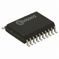
W681360SG TR Nuvoton Technology Corporation of America, W681360SG TR Datasheet - Page 12

W681360SG TR
Manufacturer Part Number
W681360SG TR
Description
IC VOICEBAND CODEC 3V 1CH 20SOP
Manufacturer
Nuvoton Technology Corporation of America
Type
PCMr
Datasheet
1.W681360YG.pdf
(34 pages)
Specifications of W681360SG TR
Data Interface
PCM Audio Interface
Resolution (bits)
13 b
Number Of Adcs / Dacs
1 / 1
Sigma Delta
No
Voltage - Supply, Analog
2.7 V ~ 5.25 V
Voltage - Supply, Digital
2.7 V ~ 5.25 V
Operating Temperature
-40°C ~ 85°C
Mounting Type
Surface Mount
Package / Case
20-SOP
For Use With
W681360ES - KIT EVAL FOR W681360
Lead Free Status / RoHS Status
Lead free / RoHS Compliant
Other names
W681360SG T&R
W681360SG T&R
W681360SG T&R
The PCM interface is controlled by pins BCLKR, FSR, BCLKT & FST. The input data is received
through the PCMR pin and the output data is transmitted through the PCMT pin.
The Long Frame Sync or Short Frame Sync interface mode can be selected by connecting the BCLKR
or BCLKT pin to a 256kHz to 4.800 MHz clock and connecting the FSR or FST pin to the 8kHz frame
sync. The device synchronizes the data word for the PCM interface and the CODEC sample rate on
the positive edge of the Frame Sync signal. Long Frame Sync is recognized when the FST pin is held
HIGH for two consecutive falling edges of the bit-clock at the BCLKT pin. Short Frame Sync Mode is
recognized when the Frame Sync signal at pin FST is HIGH for one and only one falling edge of the
bit-clock at the BCLKT pin.
The device recognizes a Long Frame Sync when the FST pin is held HIGH for two consecutive falling
edges of the bit-clock at the BCLKT pin. The length of the Frame Sync pulse can vary from frame to
frame, as long as the positive frame sync edge occurs every 125 μsec. During data transmission in the
Long Frame Sync mode, the transmit data pin PCMT will become low impedance when the Frame
Sync signal FST is HIGH or when the 13-bit data word is being transmitted. The transmit data pin
PCMT will become high impedance when the Frame Sync signal FST becomes LOW while the data is
transmitted or when half of the LSB is transmitted. The internal decision logic will determine whether
the next frame sync is a long or a short frame sync, based on the previous frame sync pulse. To avoid
bus collisions, the PCMT pin will be high impedance for two frame sync cycles after every power down
state. Long Frame Sync mode is illustrated below. More detailed timing information can be found in
the interface timing section.
The W681360 operates in the Short Frame Sync Mode when the Frame Sync signal at pin FST is
HIGH for one and only one falling edge of the bit-clock at the BCLKT pin. On the following rising edge
of the bit-clock, the W681360 starts clocking out the data on the PCMT pin, which will also change
from high to low impedance state. The data transmit pin PCMT will go back to the high impedance
state halfway through the LSB. The Short Frame Sync operation of the W681360 is based on a 13-bit
data word. When receiving data on the PCMR pin, the data is clocked in on the first falling edge after
the falling edge that coincides with the Frame Sync signal. The internal decision logic will determine
whether the next frame sync is a long or a short frame sync, based on the previous frame sync pulse.
To avoid bus collisions, the PCMT pin will be high impedance for two frame sync cycles after every
power down state. Short Frame Sync mode is illustrated below. More detailed timing information can
be found in the interface timing section.
(BCLKR)
BCLKT
7.4. PCM I
PCMR
PCMT
(FSR)
FST
7.4.1. Long Frame Sync
7.4.2. Short Frame Sync
don't care
NTERFACE
1
1
2
2
Long Frame Sync (Transmit and Receive Have Individual Clocking)
FIGURE 7.4: LONG FRAME SYNC PCM MODE
3
3
4
4
5
5
6
6
7
7
8
8
- 12 -
9
9
10
10
11
11
12
12
Publication Release Date: September 2005
13
13
don't care
W681360
Revision A.2


