LM4550BVH/NOPB National Semiconductor, LM4550BVH/NOPB Datasheet - Page 27
LM4550BVH/NOPB
Manufacturer Part Number
LM4550BVH/NOPB
Description
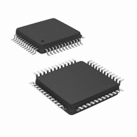
IC AC '97 AUDIO CODEC 48-LQFP
Manufacturer
National Semiconductor
Type
Audio Codec '97r
Specifications of LM4550BVH/NOPB
Data Interface
Serial
Resolution (bits)
18 b
Number Of Adcs / Dacs
2 / 2
Sigma Delta
Yes
Dynamic Range, Adcs / Dacs (db) Typ
90 / 89
Voltage - Supply, Analog
4.2 V ~ 5.5 V
Voltage - Supply, Digital
3 V ~ 5.5 V
Operating Temperature
-40°C ~ 85°C
Mounting Type
Surface Mount
Package / Case
48-LQFP
Audio Codec Type
Stereo
No. Of Adcs
2
No. Of Dacs
2
No. Of Input Channels
8
No. Of Output Channels
3
Adc / Dac Resolution
18bit
Sampling Rate
48kSPS
Interface Type
Serial
Supply Voltage Range
3V To 5.5V, 4.2V
Rohs Compliant
Yes
Lead Free Status / RoHS Status
Lead free / RoHS Compliant
Other names
*LM4550BVH
*LM4550BVH/NOPB
LM4550BVH
*LM4550BVH/NOPB
LM4550BVH
Available stocks
Company
Part Number
Manufacturer
Quantity
Price
Company:

Part Number:
LM4550BVH/NOPB
Manufacturer:
STM
Quantity:
1 872
Company:
Part Number:
LM4550BVH/NOPB
Manufacturer:
Texas Instruments
Quantity:
10 000


Multiple Codecs
the controller and any Secondary codecs. Secondary co-
decs use BIT_CLK as an input and as their timing source
and do not use XTAL_IN or XTAL_OUT, The AMAP map-
pings are given in Table 1 and the use of Tag Bits is de-
scribed below.
SECONDARY CODEC REGISTER ACCESS
For Secondary Codec access, the controller must set the tag
bits for Command Address and Data in the Output Frame as
invalid (i.e. equal to 0). The Command Address and Data tag
bits are in slot 0, bits 14 and 13 and Output Frames are
those in the SDATA_OUT signal from controller to codec.
The controller must also place the non-zero value (01, 10, or
11) corresponding to the Identity (ID1, ID0) of the target
Secondary Codec into the Codec ID field (slot 0, bits 1 and 0)
in that same Output Frame. The value set in the Codec ID
field determines which of the three possible Secondary Co-
decs is accessed. Unlike a Primary Codec, a Secondary
Codec will disregard the Command Address and Data tag
bits when there is a match between the 2-bit Codec ID value
(slot 0, bits 1 and 0) and the Codec Identity (ID1, ID0).
Instead it uses the Codec-ID/Identity match to indicate that
the Command Address in slot 1 and (if a “write”) the Com-
mand Data in slot 2 are valid.
When reading from a Secondary Codec, the controller must
send the correct Codec ID bits (i.e. the target Codec Identity
in slot 0, bits 1 and 0) along with the read-request bit (slot 1,
bit 19) and target register address (slot 1, bits 18 – 12). To
write to a Secondary Codec, a controller must send the
SLOT 0: TAG bits in Output Frames (controller to codec)
Extended Audio ID register (28h): Support for Multiple Codecs
Note 11: AC ’97 Rev 2.1 specifies this allocation of 5.1 Audio channels to these slots in the AC Link Output Frame
Bit 15
Frame
Primary
Secondary 1
Secondary 2
Secondary 3
Reg
28h
Codec Identity
Valid
Mode
Extended
Audio ID
Slot 1
Valid
Name
14
Slot 2
Valid
13
D15 D14 D13 D12 D11 D10
ID1
(D15, 28h)
Slot 3
ID1
Valid
0
0
1
1
ID0
12
(Continued)
Slot 4
X
Valid
11
(D14, 28h)
X
TABLE 1. AMAP Slot-to-DAC Audio MAPping
ID0
0
1
0
1
10
X
X
Slot 6
Valid
9
X
From Slot #
AMAP
Slot 7
Valid
D9
3
3
7
6
8
Left DAC data
27
D8
Slot 8
Valid
X
Left
Left
Left Surround
Center
7
correct Codec ID bits when slot 1 contains a valid target
register address and “write” indicator bit and slot 2 contains
valid target register data. A write operation is only valid if the
register address and data are both valid and sent within the
same frame. When accessing the Primary Codec, the Codec
ID bits are cleared and the tag bits 14 and 13 resume their
role indicating the validity of Command Address and Data in
slots 1 and 2.
The use of the tag bits in Input Frames (carried by the
SDATA_IN signal) is the same for Primary and Secondary
Codecs.
The Codec Identity is determined by the inverting input pins
ID1#, ID0# (pins 46 and 45) and can be read as the value of
the ID1, ID0 bits (D15, D14) in the Extended Audio ID
register, 28h of the target codec.
In addition to the Codec Identity bits (ID1, ID0), the read-only
Extended Audio ID register (28h) contains the AMAP bit
(D9). The AMAP bit indicates support for the (optional) AC
’97 Rev. 2.1 compliant mappings from slots in AC Link Out-
put Frames to the audio DACs for each of the four Codec
Identity modes. AMAP = 1 indicates that the default mapping
(as realized after reset) of Slots-to-DACs conforms to Table
1. Slots in AC Link Input Frames are always mapped such
that PCM data from the left ADC channel is carried by slot 3
and PCM data from the right ADC channel by slot 4. Output
Frames are those carried by the SDATA_OUT signal from
the controller to the codec while Input Frames are those
carried by the SDATA_IN signal from the codec to the
controller.
5.1 Audio channel
D7
X
Slot 9
Valid
(Note 11)
6
D6
X
D5
X
5
X
D4
X
From Slot #
X
4
D3
X
4
4
8
9
3
X
Right DAC data
D2
X
Right
Right
Right Surround
LFE
5.1 Audio channel
2
X
D1
X
(Note 11)
VRA X201h
D0
ID1
1
www.national.com
Default
ID0
0
Related parts for LM4550BVH/NOPB
Image
Part Number
Description
Manufacturer
Datasheet
Request
R

Part Number:
Description:
IC,Soundcard Circuits,QFP,48PIN,PLASTIC
Manufacturer:
National Semiconductor

Part Number:
Description:
Ac ?97 Rev 2.1 Multi-channel Audio Codec With Stereo Headphone Amplifier, Sample Rate Conversion And National 3d Sound
Manufacturer:
National Semiconductor Corporation
Datasheet:
Part Number:
Description:
National Semiconductor [8-Bit D/A Converter]
Manufacturer:
National Semiconductor
Datasheet:
Part Number:
Description:
National Semiconductor [Media Coprocessor]
Manufacturer:
National Semiconductor
Datasheet:
Part Number:
Description:
Digitally Controlled Tone and Volume Circuit with Stereo Audio Power Amplifier, Microphone Preamp Stage and National 3D Sound
Manufacturer:
National Semiconductor
Datasheet:
Part Number:
Description:
Digitally Controlled Tone and Volume Circuit with Stereo Audio Power Amplifier, Microphone Preamp Stage and National 3D Sound
Manufacturer:
National Semiconductor
Datasheet:
Part Number:
Description:
AC97 Rev 2 Codec with Sample Rate Conversion and National 3D Sound
Manufacturer:
National Semiconductor
Part Number:
Description:
Manufacturer:
National Semiconductor
Datasheet:
Part Number:
Description:
Manufacturer:
National Semiconductor
Datasheet:
Part Number:
Description:
General Purpose, Low Voltage, Low Power, Rail-to-Rail Output Operational Amplifiers
Manufacturer:
National Semiconductor
Datasheet:
Part Number:
Description:
8-bit 20 MSPS flash A/D converter.
Manufacturer:
National Semiconductor
Datasheet:
Part Number:
Description:
Low Noise Quad Operational Amplifier
Manufacturer:
National Semiconductor
Datasheet:
Part Number:
Description:
Quad Differential Line Receivers
Manufacturer:
National Semiconductor
Datasheet:
Part Number:
Description:
Quad High Speed Trapezoidal? Bus Transceiver
Manufacturer:
National Semiconductor
Datasheet: