LM4550BVH/NOPB National Semiconductor, LM4550BVH/NOPB Datasheet - Page 26
LM4550BVH/NOPB
Manufacturer Part Number
LM4550BVH/NOPB
Description
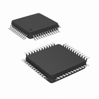
IC AC '97 AUDIO CODEC 48-LQFP
Manufacturer
National Semiconductor
Type
Audio Codec '97r
Specifications of LM4550BVH/NOPB
Data Interface
Serial
Resolution (bits)
18 b
Number Of Adcs / Dacs
2 / 2
Sigma Delta
Yes
Dynamic Range, Adcs / Dacs (db) Typ
90 / 89
Voltage - Supply, Analog
4.2 V ~ 5.5 V
Voltage - Supply, Digital
3 V ~ 5.5 V
Operating Temperature
-40°C ~ 85°C
Mounting Type
Surface Mount
Package / Case
48-LQFP
Audio Codec Type
Stereo
No. Of Adcs
2
No. Of Dacs
2
No. Of Input Channels
8
No. Of Output Channels
3
Adc / Dac Resolution
18bit
Sampling Rate
48kSPS
Interface Type
Serial
Supply Voltage Range
3V To 5.5V, 4.2V
Rohs Compliant
Yes
Lead Free Status / RoHS Status
Lead free / RoHS Compliant
Other names
*LM4550BVH
*LM4550BVH/NOPB
LM4550BVH
*LM4550BVH/NOPB
LM4550BVH
Available stocks
Company
Part Number
Manufacturer
Quantity
Price
Company:

Part Number:
LM4550BVH/NOPB
Manufacturer:
STM
Quantity:
1 872
Company:
Part Number:
LM4550BVH/NOPB
Manufacturer:
Texas Instruments
Quantity:
10 000


www.national.com
Low Power Modes
ticular the startup time of the V
value of the decoupling capacitors on pin 27 (3.3 µF, 0.1 µF
in parallel is recommended).
When the AC Link Digital Interface is powered down the
codec output signals SDATA_IN and BIT_CLK (Primary
mode) are cleared to zero and no control data can be passed
between controller and codec(s). This powerdown state can
be cleared in two ways: Cold Reset (RESET# = 0) or Warm
Reset (SYNC = 1, no BIT_CLK). Cold Reset sets all regis-
ters back to their default values (including clearing PR4)
Improving System Performance
The audio codec is capable of dynamic range performance
in excess of 90 db., but the user must pay careful attention to
several factors to achieve this. A primary consideration is
keeping analog and digital grounds separate, and connect-
ing them together in only one place. Some designers show
the connection as a zero ohm resistor, which allows naming
the nets separately. Although it is possible to use a two layer
board, it is recommended that a minimum of four layers be
used, with the two inside layers being analog ground and
digital ground. If EMI is a system consideration, then as
many as eight layers have been successfully used. The 12
and 25 MHz. clocks can have significant harmonic content
depending on the rise and fall times. With the exception of
the digital VDD pins, (covered later) bypass capacitors
should be very close to the package. The analog VDD pins
should be supplied from a separate regulator to reduce
noise. By operating the digital portion on 3.3V instead of 5V,
an additional 0.5-0.7 db improvement can be obtained.
Depending on power supply layout, routing, and capacitor
ESR, a device instability can occur, resulting in increased
noise on the outputs. This can be eliminated by adding an
inductor in the digital supply line between the supply bypass
capacitors and the DVDD pins, which increases the high
frequency impedance of the supply as seen by the part. This
“current starving” technique slows down internal rise and fall
times, which will improve the signal to noise ratio, especially
at low temperatures. In addition, the EMI radiated from the
board is also reduced.
REF
(Continued)
circuitry depends on the
FIGURE 8. AC Link Powerdown Timing
26
whereas Warm Reset only clears the PR4 bit and restarts
the AC Link Digital Interface leaving all register contents
otherwise unaffected. For Warm Reset (see Timing Dia-
grams), the SYNC input is used asynchronously. The
LM4550 codec allows the AC Link digital interface power-
down state to be cleared immediately so that its duration can
essentially be as short as T
However for conformance with AC ’97 Rev 2.1, Warm Reset
should not be applied within 4 frame times of powerdown i.e.
the AC Link powerdown state should be allowed to last at
least 82.8 µs.
Multiple Codecs
EXTENDED AC LINK
Up to four codecs can be supported on the extended AC
Link. These multiple codec implementations should run off a
common BIT_CLK generated by the Primary Codec. All
codecs share the AC ’97 Digital Controller output signals,
SYNC, SDATA_OUT, and RESET#. Each codec, however,
supplies its own SDATA_IN signal back to the controller, with
the result that the controller requires one dedicated input pin
per codec (Figure 9).
By definition there can be one Primary Codec and up to
three Secondary Codecs on an extended AC Link. The
Primary Codec has a Codec Identity = (ID1, ID0) = ID = 00
while Secondary Codecs take identities equal to 01, 10 or 11
(see Table 1). The Codec Identity is also used as a chip
select function. This allows the Command and Status regis-
ters in any of the codecs to be individually addressed al-
though the access mechanism for Secondary Codecs differs
slightly from that for a Primary.
The Identity control pins, ID1#, ID0# (pins 46 and 45) are
internally pulled up to DV
configured as ’Primary’ either by leaving ID1#, ID0# open
(NC) or by strapping them externally to DV
The difference between Primary and Secondary codec
modes is: in their timing source; in the AMAP Slot-to-DAC
mapping used in Output Frames carried by SDATA_OUT;
and in the Tag Bit handling in Output Frames for Command/
Status register access. For a timing source, a Primary codec
divides down by 2 the frequency of the signal on XTAL_IN
and also generates this as the BIT_CLK output for the use of
DD
SH
. The Codec may therefore be
, the Warm Reset pulse width.
10097209
DD
(digital supply).
Related parts for LM4550BVH/NOPB
Image
Part Number
Description
Manufacturer
Datasheet
Request
R

Part Number:
Description:
IC,Soundcard Circuits,QFP,48PIN,PLASTIC
Manufacturer:
National Semiconductor

Part Number:
Description:
Ac ?97 Rev 2.1 Multi-channel Audio Codec With Stereo Headphone Amplifier, Sample Rate Conversion And National 3d Sound
Manufacturer:
National Semiconductor Corporation
Datasheet:
Part Number:
Description:
National Semiconductor [8-Bit D/A Converter]
Manufacturer:
National Semiconductor
Datasheet:
Part Number:
Description:
National Semiconductor [Media Coprocessor]
Manufacturer:
National Semiconductor
Datasheet:
Part Number:
Description:
Digitally Controlled Tone and Volume Circuit with Stereo Audio Power Amplifier, Microphone Preamp Stage and National 3D Sound
Manufacturer:
National Semiconductor
Datasheet:
Part Number:
Description:
Digitally Controlled Tone and Volume Circuit with Stereo Audio Power Amplifier, Microphone Preamp Stage and National 3D Sound
Manufacturer:
National Semiconductor
Datasheet:
Part Number:
Description:
AC97 Rev 2 Codec with Sample Rate Conversion and National 3D Sound
Manufacturer:
National Semiconductor
Part Number:
Description:
Manufacturer:
National Semiconductor
Datasheet:
Part Number:
Description:
Manufacturer:
National Semiconductor
Datasheet:
Part Number:
Description:
General Purpose, Low Voltage, Low Power, Rail-to-Rail Output Operational Amplifiers
Manufacturer:
National Semiconductor
Datasheet:
Part Number:
Description:
8-bit 20 MSPS flash A/D converter.
Manufacturer:
National Semiconductor
Datasheet:
Part Number:
Description:
Low Noise Quad Operational Amplifier
Manufacturer:
National Semiconductor
Datasheet:
Part Number:
Description:
Quad Differential Line Receivers
Manufacturer:
National Semiconductor
Datasheet:
Part Number:
Description:
Quad High Speed Trapezoidal? Bus Transceiver
Manufacturer:
National Semiconductor
Datasheet: