LM4550BVH/NOPB National Semiconductor, LM4550BVH/NOPB Datasheet - Page 13
LM4550BVH/NOPB
Manufacturer Part Number
LM4550BVH/NOPB
Description
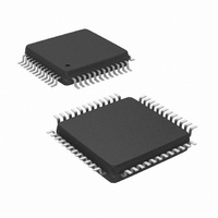
IC AC '97 AUDIO CODEC 48-LQFP
Manufacturer
National Semiconductor
Type
Audio Codec '97r
Specifications of LM4550BVH/NOPB
Data Interface
Serial
Resolution (bits)
18 b
Number Of Adcs / Dacs
2 / 2
Sigma Delta
Yes
Dynamic Range, Adcs / Dacs (db) Typ
90 / 89
Voltage - Supply, Analog
4.2 V ~ 5.5 V
Voltage - Supply, Digital
3 V ~ 5.5 V
Operating Temperature
-40°C ~ 85°C
Mounting Type
Surface Mount
Package / Case
48-LQFP
Audio Codec Type
Stereo
No. Of Adcs
2
No. Of Dacs
2
No. Of Input Channels
8
No. Of Output Channels
3
Adc / Dac Resolution
18bit
Sampling Rate
48kSPS
Interface Type
Serial
Supply Voltage Range
3V To 5.5V, 4.2V
Rohs Compliant
Yes
Lead Free Status / RoHS Status
Lead free / RoHS Compliant
Other names
*LM4550BVH
*LM4550BVH/NOPB
LM4550BVH
*LM4550BVH/NOPB
LM4550BVH
Available stocks
Company
Part Number
Manufacturer
Quantity
Price
Company:

Part Number:
LM4550BVH/NOPB
Manufacturer:
STM
Quantity:
1 872
Company:
Part Number:
LM4550BVH/NOPB
Manufacturer:
Texas Instruments
Quantity:
10 000


Pin Descriptions
RESET#
Name
SYNC
EAPD
ID0#
ID1#
CIN
Pin
10
11
45
46
47
48
I / O
O
I
I
I
I
I
(Continued)
AC Link frame marker and Warm Reset
This input defines the boundaries of AC Link frames. Each frame lasts 256 periods of
BIT_CLK. In normal operation SYNC is a 48 kHz positive pulse with a duty cycle of 6.25%
(16/256). SYNC is sampled on the falling edge of BIT_CLK and the codec takes the first
positive sample of SYNC as defining the start of a new AC Link frame. If a subsequent SYNC
pulse occurs within 255 BIT_CLK periods of the frame start it will be ignored.
SYNC is also used as an active high input to perform an (asynchronous) Warm Reset. Warm
Reset is used to clear a power down state on the codec AC Link interface.
Cold Reset
This active low signal causes a hardware reset which returns the control registers and all
internal circuits to their default conditions. RESET# MUST be used to initialize the LM4550B
after Power On when the supplies have stabilized. Cold Reset also clears the codec from
both ATE and Vendor test modes. In addition, while active, it switches the PC_BEEP mono
input directly to both channels of the LINE_OUT stereo output.
Codec Identity
ID1# and ID0# determine the Codec Identity for multiple codec use. The Codec Identity
configures the codec in either Primary or one of three Secondary Codec modes. These
Identity pins are of inverted polarity relative to the Codec Identity bits ID1, ID0 (bits D15, D14)
in the read-only Extended Audio ID register, 28h. If the ID0# pin (pin 45) is connected to
ground then the ID0 bit (D14, reg 28h) will be set to “1”. Similarly, connection to DV
the ID0 bit to “0”. If left open (NC), ID0# is pulled high by an internal pull-up resistor. The
Codec Identity bits are also used in the Chain-In Control register, 74h. See the register
description and the CIN pin description for details.
Codec Identity
ID1# and ID0# determine the codec address for multiple codec use. The Codec Identity
configures the codec in either Primary or one of three Secondary Codec modes. These
Identity pins are of inverted polarity relative to the Codec Identity bits ID1, ID0 (bits D15, D14)
in the read-only Extended Audio ID register, 28h. If the ID1# pin (pin 46) is connected to
ground then the ID1 bit (D15, reg 28h) will be set to “1”. Similarly, connection to DV
the ID1 bit to “0”. If left open (NC), ID1# is pulled high by an internal pull-up resistor. The
Codec Identity bits are also used in the Chain-In Control register, 74h. See the register
description and the CIN pin description for details.
External Amplifier Power Down control signal
This output is set by the EAPD bit (bit D15) in the Powerdown Control/Status register, 26h. As
with the other logic outputs, the output voltage is set by DV
connected to the shutdown pin on an external power amplifier. For normal operation the
default value of EAPD = 0 will enable the external amplifier allowing an input on PC_BEEP to
be heard during Cold Reset.
Chain In
The codec can be instructed to disconnect its own SDATA_IN signal and instead pass the
signal on CIN through to the SDATA_IN output pin. This is achieved by changing the value of
the two LSBs of the Chain-In Control register (74h) so that they differ from the Codec Identity
bits ID1, ID0. Those two LSBs default to the value of the Codec Identity bits following Cold
Reset thereby disabling the Chain In feature. Chain In can also be disabled by reading the
Codec Identity from the Extended Audio ID register (28h) and writing the value back into
register 74h LSBs. The Codec Identity bits are determined by the input pins ID1#, ID0#.
CIN can be left open (NC) provided that the chain feature is disabled. When the chain feature
is used, CIN should always be driven. Either connect the SDATA_IN pin from another codec
or else ground CIN to prevent the possibility of floating the SDATA_IN signal at the controller.
DIGITAL I/O AND CLOCKING (Continued)
13
Functional Description
DD
. This pin is intended to be
www.national.com
DD
DD
will set
will set
Related parts for LM4550BVH/NOPB
Image
Part Number
Description
Manufacturer
Datasheet
Request
R

Part Number:
Description:
IC,Soundcard Circuits,QFP,48PIN,PLASTIC
Manufacturer:
National Semiconductor

Part Number:
Description:
Ac ?97 Rev 2.1 Multi-channel Audio Codec With Stereo Headphone Amplifier, Sample Rate Conversion And National 3d Sound
Manufacturer:
National Semiconductor Corporation
Datasheet:
Part Number:
Description:
National Semiconductor [8-Bit D/A Converter]
Manufacturer:
National Semiconductor
Datasheet:
Part Number:
Description:
National Semiconductor [Media Coprocessor]
Manufacturer:
National Semiconductor
Datasheet:
Part Number:
Description:
Digitally Controlled Tone and Volume Circuit with Stereo Audio Power Amplifier, Microphone Preamp Stage and National 3D Sound
Manufacturer:
National Semiconductor
Datasheet:
Part Number:
Description:
Digitally Controlled Tone and Volume Circuit with Stereo Audio Power Amplifier, Microphone Preamp Stage and National 3D Sound
Manufacturer:
National Semiconductor
Datasheet:
Part Number:
Description:
AC97 Rev 2 Codec with Sample Rate Conversion and National 3D Sound
Manufacturer:
National Semiconductor
Part Number:
Description:
Manufacturer:
National Semiconductor
Datasheet:
Part Number:
Description:
Manufacturer:
National Semiconductor
Datasheet:
Part Number:
Description:
General Purpose, Low Voltage, Low Power, Rail-to-Rail Output Operational Amplifiers
Manufacturer:
National Semiconductor
Datasheet:
Part Number:
Description:
8-bit 20 MSPS flash A/D converter.
Manufacturer:
National Semiconductor
Datasheet:
Part Number:
Description:
Low Noise Quad Operational Amplifier
Manufacturer:
National Semiconductor
Datasheet:
Part Number:
Description:
Quad Differential Line Receivers
Manufacturer:
National Semiconductor
Datasheet:
Part Number:
Description:
Quad High Speed Trapezoidal? Bus Transceiver
Manufacturer:
National Semiconductor
Datasheet: