APF30-30-10CB CTS, APF30-30-10CB Datasheet - Page 13
APF30-30-10CB
Manufacturer Part Number
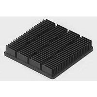
APF30-30-10CB
Description
Heatsinks 30x30x10mm
Manufacturer
CTS
Datasheet
1.Z3A45SBSBNR.pdf
(24 pages)
Specifications of APF30-30-10CB
Product
Heatsinks
Mounting Style
SMD/SMT
Heatsink Material
Black Anodized
Fin Style
Horizontal
Thermal Resistance
3.25 C /W
Dimensions
30 mm L x 30 mm W x 9.5 mm H
Designed For
BGA, PGA, PLCC, QFP
Color
Black


6.35mm
.250”
9.14mm
ORDERING INFORMATION
are available in several standard
configurations.When ordering
standard ZIF assemblies, kits
or individual components,
please refer to the ZIF identi-
fication number guide shown
above. Custom ZIF retainers
will be assigned special part
number identification.
.036”
①
ZIF Designation
Assembly Option
A=Assembled K=Kit
Mounting Method
B=Brazed
S=Screws 4-40
M=Metric Screws (M3x0.5)
Housing Series
1=Without Pins
2=With .062x.040
Rod Assembly
1=Pin Drive, Aluminum Rod (6” Max.)
2=Pin Drive, Steel Rod
3=Slot Drive, Steel Rod (4.5” Max.)
4=1/4 Hex Drive, Aluminum Rod
7=3/16 Hex Drive, Steel Rod
①
①
Spring Series
1=Current Design
Board Thickness (±.005 Max.)
ROD STYLES
DESIG.
ZRA1
ZRA2
ZRA3
ZRA4
ZRA7
.031”
ZRAS
S=3/16 Hex Drive, Steel Rod
Z=1/8” Socket Head Cap, Steel Rod
Extended Aluminum Index Pins
ZIF circuit board retainers
7.9375mm
.3125”
(Screwdriver Slot Drive)
(1/4” Hexhead Drive)
.050”
FIG. NO.
(Pin Drive)
Fig. 2
Fig. 3
Fig. 1
4
1
1
2
3
4
.062”
ROD TYPE
.20”
5.08mm
aluminum
aluminum
.250”
6.35mm
.125”
3.175mm
MATERIAL
steel
steel
steel
steel
.250”
6.35mm
.084”
4.7625mm
5.558mm
.1875”
WRENCH
.220”
ALLEN
.125”
.093”
MAX. SPRING LENGTH
BOARD
1.575mm 1.600mm 10.16mm
2.134mm 1.600mm 10.719mm
2.362mm 2.007mm 11.354mm
3.175mm 2.083mm 12.141mm
THICK
.787mm 2.388mm 10.16mm
1.27mm 1.905mm 10.16mm
.031”
.050”
.062”
.084”
.093”
.125”
10.5 inches
10.5 inches
10.5 inches
10.5 inches
4.5 inches
Z A S 1 1 1 - 0 6 2 - 1 5 R * - B B U
(1/8” Socket Head Cap)
6 inches
(3/16” Hexhead Drive)
Visual Identification Slot
.125”
.094”
.075”
.063”
.063”
.079”
.082”
REF
K
Fig. 5
Fig. 4
MAX
.400”
.400”
.400”
.422”
.447”
.478”
.15”
3.81mm
L
.250”
6.35mm
.250”
6.35mm
All dimensions are in inches unless otherwise noted.
DESIGNATION LENGTH ±.005
K REF
LENGTH
9.779±.254mm
.175-.195”
4.445-4.953mm
BOARD INSERTION DEPTH
.385±.010”
03
04
05
06
07
08
09
10
11
12
13
14
15
16
17
18
19
20
21
ZIF HOUSING DIMENSIONS
SPRING
10.5
*All assembled ZIFs must have a left or right designation.
Any kit with a 1/4 inch hexhead drive must have a left or right designation.
①
1.5
1.5
1.5
4.5
4.5
4.5
7.5
7.5
7.5
3
3
3
6
6
6
9
9
9
Visual identification slot painted yellow.
10.00
10.50
1.50
2.00
2.50
3.00
3.50
4.00
4.50
5.00
5.50
6.00
6.50
7.00
7.50
8.00
8.50
9.00
9.50
.040”
1.016mm
ON TYPE 2
HOUSING ONLY
12.7mm
A
L MAX
6.35mm
*.50”
*.25”
1.00 — 1.00 1.75 —
1.25 — 1.50 2.25 —
1.00 1.5 2.50 1.75 3.25 —
1.25 1.5 3.00 2.00 3.75 —
1.00 3.0 4.00 1.75 3.25 4.75 —
1.25 3.0 4.50 2.00 3.50 5.25 —
1.00 4.5 5.50 2.25 4.25 6.25 —
1.25 4.5 6.00 2.50 4.50 6.75 —
2.25 3.0 6.50 2.00 3.75 5.50 7.25 —
2.50 3.0 7.00 2.00 4.00 6.00 7.25 —
2.75 3.0 7.50 2.25 4.25 6.25 8.25 —
3.75 1.5 8.00 2.50 4.50 6.50 8.75 —
4.00 1.5 8.50 2.00 3.75 5.75 7.50 9.25
4.25 1.5 9.00 2.00 4.00 6.00 8.00 9.75
5.25 — 9.50 2.25 4.25 6.25 8.25 10.25
.75
.75 1.5 2.00 1.50 2.75 —
.75 3.0 3.50 2.25 4.25 —
.75 4.5 5.00 2.00 4.00 5.75 —
B
*
TOLERANCE ±.005
— .50 1.25 —
C
B
*E
*F
D
*G
*H
Assembly Length in .5” Increments x 2
Ex: 7.5”=15
R=Right Hand Part
L=Left Hand Part
4-40 MOUNTING HOLES
E
A±.005
*J
Housing Plating
B=Black Anodize
U=Unplated
R=Chem. Film
C
F
Rod Plating
B=Black Anod. Aluminum Rods
P=Passivated, Steel Rods
Spring Plating
U=Unplated
B=Black Cadmium
N=Nickel
—
—
—
G
—
—
—
—
—
—
—
H
—
—
—
—
—
—
—
—
—
—
—
—
J
SCREW MOUNTED
PARTS ONLY
TYPE 1 HOUSING
.062”
(2 PLC ALL PARTS)
(LOCATING PIN HOLES)
TYPE 2 HOUSING
.062 x .040”
1.5748 x 1.016mm
EXTENDED ALUMINUM
INDEX PINS
CTS
MNTG.HOLES
—.001
+.002
.125 MIN DEEP
NO. OF
DIA. x
2
2
2
3
3
3
3
4
4
4
4
4
5
5
5
5
6
6
6
13
®
Related parts for APF30-30-10CB
Image
Part Number
Description
Manufacturer
Datasheet
Request
R

Part Number:
Description:
Heatsinks 30x30x6mm Double-sided Kapton
Manufacturer:
CTS
Datasheet:
Part Number:
Description:
Heatsinks 30x30x13mm
Manufacturer:
CTS
Datasheet:
Part Number:
Description:
Heatsinks 30x30x6mm
Manufacturer:
CTS
Datasheet:
Part Number:
Description:
Heatsinks 30x30x13mm Double-sided Kapton
Manufacturer:
CTS
Datasheet:

Part Number:
Description:
HEATSINK FORGED W/ADHESIVE TAPE
Manufacturer:
CTS Thermal Management Products
Datasheet:


Part Number:
Description:
Amplifier, CTS Series Public Address
Manufacturer:
BOGEN COMMUNICATIONS
Datasheet:


Part Number:
Description:
CRYSTAL 11.0592 MHZ SERIES
Manufacturer:
CTS-Frequency Controls
Datasheet:
Part Number:
Description:
CRYSTAL 20.000 MHZ SERIES
Manufacturer:
CTS-Frequency Controls
Datasheet:

Part Number:
Description:
RES NET 15RES 4.7K OHM 16PIN SMD
Manufacturer:
CTS Resistor Products
Datasheet:
Part Number:
Description:
VOLTAGE CONTROLLED CRYSTAL OSCILLATOR
Manufacturer:
CTS Electronic Components, Inc.