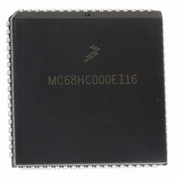
MC68HC000EI16 Freescale Semiconductor, MC68HC000EI16 Datasheet - Page 71

MC68HC000EI16
Manufacturer Part Number
MC68HC000EI16
Description
IC MPU 32BIT 16MHZ 68-PLCC
Manufacturer
Freescale Semiconductor
Specifications of MC68HC000EI16
Processor Type
M680x0 32-Bit
Speed
16MHz
Voltage
3.3V, 5V
Mounting Type
Surface Mount
Package / Case
68-PLCC
Family Name
M68000
Device Core
ColdFire
Device Core Size
16/32Bit
Frequency (max)
16MHz
Instruction Set Architecture
RISC
Supply Voltage 1 (typ)
5V
Operating Supply Voltage (max)
5.25V
Operating Supply Voltage (min)
4.75V
Operating Temp Range
0C to 70C
Operating Temperature Classification
Commercial
Mounting
Surface Mount
Pin Count
68
Package Type
PLCC
Lead Free Status / RoHS Status
Lead free / RoHS Compliant
Features
-
Lead Free Status / Rohs Status
Compliant
Available stocks
Company
Part Number
Manufacturer
Quantity
Price
Company:
Part Number:
MC68HC000EI16
Manufacturer:
TI
Quantity:
604
Company:
Part Number:
MC68HC000EI16
Manufacturer:
FREESCALE
Quantity:
2 900
Company:
Part Number:
MC68HC000EI16
Manufacturer:
Freescale Semiconductor
Quantity:
10 000
Company:
Part Number:
MC68HC000EI16R2
Manufacturer:
FREESCAL
Quantity:
8 831
Company:
Part Number:
MC68HC000EI16R2
Manufacturer:
Freescale Semiconductor
Quantity:
10 000
After the aborted bus cycle is terminated and BERR is negated, the processor enters
exception processing for the bus error exception. During the exception processing
sequence, the following information is placed on the supervisor stack:
The first two items are identical to the information stacked by any other exception. The
error information differs for the MC68010. The MC68000, MC68HC000, MC68HC001,
MC68EC000, and MC68008 stack bus error information to help determine and to correct
the error. The MC68010 stacks the frame format and the vector offset followed by 22
words of internal register information. The return from exception (RTE) instruction restores
the internal register information so that the MC68010 can continue execution of the
instruction after the error handler routine completes.
After the processor has placed the required information on the stack, the bus error
exception vector is read from vector table entry 2 (offset $08) and placed in the program
counter. The processor resumes execution at the address in the vector, which is the first
instruction in the bus error handler routine.
MOTOROLA
1. Status register
2. Program counter (two words, which may be up to five words past the instruction
3. Error information
being executed)
FC2–FC0
UDS/LDS
D15–D0
A23–A1
DTACK
BERR
HALT
R/W
CLK
AS
Figure 5-26. Delayed Bus Error Timing Diagram (MC68010)
M68000 8-/16-/32-BIT MICROPROCESSORS USER'S MANUAL
S0
READ CYCLE
S2
S4
S6
BUS ERROR
DETECTION
ERROR STACKING
INITIATE BUS
5- 25


