MPC8247VRMIBA Freescale Semiconductor, MPC8247VRMIBA Datasheet - Page 15
MPC8247VRMIBA
Manufacturer Part Number
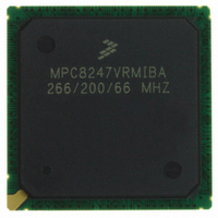
MPC8247VRMIBA
Description
IC MPU POWERQUICC II 516-PBGA
Manufacturer
Freescale Semiconductor
Series
PowerQUICC IIr
Datasheet
1.MPC8248VRMIBA.pdf
(60 pages)
Specifications of MPC8247VRMIBA
Processor Type
MPC82xx PowerQUICC II 32-bit
Speed
266MHz
Voltage
1.5V
Mounting Type
Surface Mount
Package / Case
516-PBGA
Family Name
MPC82XX
Device Core
PowerQUICC II
Device Core Size
32b
Frequency (max)
266MHz
Instruction Set Architecture
RISC
Supply Voltage 1 (typ)
1.5V
Operating Supply Voltage (max)
1.575V
Operating Supply Voltage (min)
1.425V
Operating Temp Range
0C to 105C
Operating Temperature Classification
Commercial
Mounting
Surface Mount
Pin Count
516
Package Type
TEPBGA
Processor Series
MPC8xxx
Core
603e
Data Bus Width
32 bit
Maximum Clock Frequency
266 MHz
Operating Supply Voltage
1.4 V to 1.6 V
Maximum Operating Temperature
+ 105 C
Mounting Style
SMD/SMT
Data Ram Size
4 KB
I/o Voltage
3.3 V
Interface Type
I2C, SPI, UART
Minimum Operating Temperature
- 40 C
Number Of Programmable I/os
14
Program Memory Size
16 KB
Program Memory Type
EEPROM
Core Size
32 Bit
Cpu Speed
266MHz
Digital Ic Case Style
BGA
No. Of Pins
516
Supply Voltage Range
1.425V To 1.575V
Rohs Compliant
Yes
For Use With
CWH-PPC-8248N-VE - KIT EVAL SYSTEM QUICCSTART 8248
Lead Free Status / RoHS Status
Lead free / RoHS Compliant
Features
-
Lead Free Status / Rohs Status
Compliant
Available stocks
Company
Part Number
Manufacturer
Quantity
Price
Company:

Part Number:
MPC8247VRMIBA
Manufacturer:
FREESCALE
Quantity:
101
Company:
Part Number:
MPC8247VRMIBA
Manufacturer:
FREESCAL
Quantity:
748
Company:
Part Number:
MPC8247VRMIBA
Manufacturer:
Freescale Semiconductor
Quantity:
10 000
Part Number:
MPC8247VRMIBA
Manufacturer:
FREESCALE
Quantity:
20 000
Company:
Part Number:
MPC8247VRMIBA266/200/66
Manufacturer:
FREESCAL
Quantity:
717


5
Table 7
thermal management is required to ensure the junction temperature does not exceed the maximum
specified value. Also note that the I/O power should be included when determining whether to use a heat
sink. For a complete list of possible clock configurations, refer to
Modes.”
Freescale Semiconductor
JEDEC Specifications
1. C.E. Triplett and B. Joiner, “An Experimental Characterization of a 272 PBGA Within an
2. B. Joiner and V. Adams, “Measurement and Simulation of Junction to Board Thermal Resistance
1
2
3
66.7 MHz = 0.35 W (nominal), 0.4 W (maximum)
83.3 MHz = 0.4 W (nominal), 0.5 W (maximum)
100 MHz = 0.5 W (nominal), 0.6 W (maximum)
133 MHz = 0.7 W (nominal), 0.8 W (maximum)
Test temperature = 105
P
Values do not include I/O. Add the following estimates for active I/O based on the following bus speeds:
Automotive Engine Controller Module,” Proceedings of SemiTherm, San Diego, 1998, pp. 47–54.
and Its Application in Thermal Modeling,” Proceedings of SemiTherm, San Diego, 1999, pp.
212–220.
Power Dissipation
INT
provides preliminary, estimated power dissipation for various configurations. Note that suitable
= I
(MHz)
66.67
Bus
100
100
133
DD
x V
DD
Table 7. Estimated Power Dissipation for Various Configurations
Watts
MPC8272 PowerQUICC II™ Family Hardware Specifications, Rev. 2
Multiplication
°
C
Factor
CPM
3
2
2
2
(MHz)
CPM
200
200
200
267
Multiplication
Factor
CPU
4
3
4
3
Section 7, “Clock Configuration
(MHz)
CPU
266
300
400
400
http://www.jedec.org
Nominal
1.1
1.3
1.5
1
Vddl 1.5 Volts
1
P
INT
(W)
Power Dissipation
Maximum
2, 3
1.2
1.3
1.5
1.8
15
Related parts for MPC8247VRMIBA
Image
Part Number
Description
Manufacturer
Datasheet
Request
R

Part Number:
Description:
Manufacturer:
Freescale Semiconductor, Inc
Datasheet:
Part Number:
Description:
Manufacturer:
Freescale Semiconductor, Inc
Datasheet:
Part Number:
Description:
Manufacturer:
Freescale Semiconductor, Inc
Datasheet:
Part Number:
Description:
Manufacturer:
Freescale Semiconductor, Inc
Datasheet:
Part Number:
Description:
Manufacturer:
Freescale Semiconductor, Inc
Datasheet:
Part Number:
Description:
Manufacturer:
Freescale Semiconductor, Inc
Datasheet:
Part Number:
Description:
Manufacturer:
Freescale Semiconductor, Inc
Datasheet:
Part Number:
Description:
Manufacturer:
Freescale Semiconductor, Inc
Datasheet:
Part Number:
Description:
Manufacturer:
Freescale Semiconductor, Inc
Datasheet:
Part Number:
Description:
Manufacturer:
Freescale Semiconductor, Inc
Datasheet:
Part Number:
Description:
Manufacturer:
Freescale Semiconductor, Inc
Datasheet:
Part Number:
Description:
Manufacturer:
Freescale Semiconductor, Inc
Datasheet:
Part Number:
Description:
Manufacturer:
Freescale Semiconductor, Inc
Datasheet:
Part Number:
Description:
Manufacturer:
Freescale Semiconductor, Inc
Datasheet:
Part Number:
Description:
Manufacturer:
Freescale Semiconductor, Inc
Datasheet: