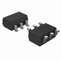
PIC10F202T-I/OT Microchip Technology, PIC10F202T-I/OT Datasheet - Page 38

PIC10F202T-I/OT
Manufacturer Part Number
PIC10F202T-I/OT
Description
IC PIC MCU FLASH 512X12 SOT23-6
Manufacturer
Microchip Technology
Series
PIC® 10Fr
Datasheets
1.PIC10F200T-IOT.pdf
(96 pages)
2.PIC10F200T-IOT.pdf
(6 pages)
3.PIC10F200T-IOT.pdf
(18 pages)
4.PIC10F202-EP.pdf
(88 pages)
5.AC162052.pdf
(54 pages)
Specifications of PIC10F202T-I/OT
Program Memory Type
FLASH
Program Memory Size
768B (512 x 12)
Package / Case
SOT-23-6
Core Processor
PIC
Core Size
8-Bit
Speed
4MHz
Peripherals
POR, WDT
Number Of I /o
3
Ram Size
24 x 8
Voltage - Supply (vcc/vdd)
2 V ~ 5.5 V
Oscillator Type
Internal
Operating Temperature
-40°C ~ 85°C
Processor Series
PIC10F
Core
PIC
Data Bus Width
8 bit
Data Ram Size
24 B
Interface Type
USB
Maximum Clock Frequency
4 MHz
Number Of Programmable I/os
4
Number Of Timers
1
Operating Supply Voltage
2 V to 5.5 V
Maximum Operating Temperature
+ 85 C
Mounting Style
SMD/SMT
3rd Party Development Tools
52715-96, 52716-328, 52717-734
Development Tools By Supplier
PG164130, DV164035, DV244005, DV164005, PG164120
Minimum Operating Temperature
- 40 C
Package
6SOT-23
Device Core
PIC
Family Name
PIC10
Maximum Speed
4 MHz
Lead Free Status / RoHS Status
Lead free / RoHS Compliant
For Use With
AC162059 - HEADER INTRFC MPLAB ICD2 8/14PINAC163020 - ADAPTER PROGRAMMER PIC10F2XXAC164321 - MODULE SKT 6L PM3 SOT23AC164037 - MODULE SKT 6L PROMATE II SOT23
Eeprom Size
-
Data Converters
-
Connectivity
-
Lead Free Status / Rohs Status
Lead free / RoHS Compliant
Other names
PIC10F202T-I/OTTR
Available stocks
Company
Part Number
Manufacturer
Quantity
Price
Company:
Part Number:
PIC10F202T-I/OT
Manufacturer:
Microchip Technology
Quantity:
59 517
Company:
Part Number:
PIC10F202T-I/OT
Manufacturer:
AUO
Quantity:
409 876
Part Number:
PIC10F202T-I/OT
Manufacturer:
MICROCHIR
Quantity:
20 000
Part Number:
PIC10F202T-I/OTVAO
Manufacturer:
MICROCHIP/微芯
Quantity:
20 000
Optional Headers
AC162078
DS51292R-page 38
Header Identification
The header AC number is used for ordering the header. However, this number is not
on the header board, as the board is often used for multiple headers by inserting
different ICE/ICD devices. To identify this header board, use the following information.
Header Setup and Operation
This header board can be used with the following targets:
1. Customer target board for PIC18F1230/1330 devices. The target board should
2. PICDEM MC motor control demo board. Use the 28-pin DIP socket on both
3. PICDEM MC LV motor control demo board. Use the 28-pin DIP socket on both
The following sections detail the configuration of the jumpers on the header board for
use with the above mentioned boards.
CUSTOMER TARGET BOARD
The default configuration is to remove all jumpers.
S1 is not populated and should not be used.
After the header board is set up, do the following:
1. Connect the header to the target board.
2. Power the target board. You should see the red LED on the header board turn on.
3. Connect the debug tool to the header board.
4. Use MPLAB IDE and the debug tool to develop your application.
have an 18-pin DIP socket to connect to the 18-pin DIP socket on the header
board.
boards to mount the header board on to the PICDEM MC board.
boards to mount the header board on to the PICDEM MC LV board.
AC162078
Header
PIC18F1330-ICD
ICE/ICD Device
02-01896
Board Assembly Number
© 2009 Microchip Technology Inc.


