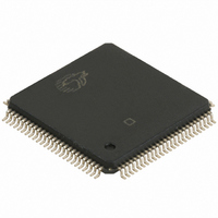
CY7C67300-100AXE Cypress Semiconductor Corp, CY7C67300-100AXE Datasheet - Page 56

CY7C67300-100AXE
Manufacturer Part Number
CY7C67300-100AXE
Description
IC USB HOST/PERIPH CNTRL 100LQFP
Manufacturer
Cypress Semiconductor Corp
Series
EZ-Host™r
Datasheet
1.CY7C67300-100AXI.pdf
(99 pages)
Specifications of CY7C67300-100AXE
Applications
USB Host/Peripheral Controller
Core Processor
CY16
Program Memory Type
ROM (8 kB)
Controller Series
CY7C673xx
Ram Size
16K x 8
Interface
SPI Serial, USB, HPI
Number Of I /o
32
Voltage - Supply
3 V ~ 3.6 V
Operating Temperature
-40°C ~ 125°C
Mounting Type
Surface Mount
Package / Case
100-LQFP
For Use With
CY4640 - KIT MASS STORAGE REF DESIGNCY3663 - KIT DEV EZ-OTG/EZ-HOST
Lead Free Status / RoHS Status
Lead free / RoHS Compliant
HSS Control Register [0xC070] [R/W]
Table 90. HSS Control Register
Register Description
The HSS Control register provides high level status and control
over the HSS port.
HSS Enable (Bit 15)
The HSS Enable bit enables or disables HSS operation.
1: Enables HSS operation
0: Disables HSS operation
RTS Polarity Select (Bit 14)
The RTS Polarity Select bit selects the polarity of RTS.
1: RTS is true when LOW
0: RTS is true when HIGH
CTS Polarity Select (Bit 13)
The CTS Polarity Select bit selects the polarity of CTS.
1: CTS is true when LOW
0: CTS is true when HIGH
XOFF (Bit 12)
The XOFF bit is a read only bit that indicates if an XOFF was
received. This bit is automatically cleared when an XON is
received.
1: XOFF received
0: XON received
XOFF Enable (Bit 11)
The XOFF Enable bit enables or disables XON/XOFF software
handshaking.
1: Enable XON/XOFF software handshaking
0: Disable XON/XOFF software handshaking
CTS Enable (Bit 10)
The CTS Enable bit enables or disables CTS/RTS hardware
handshaking.
1: Enable CTS/RTS hardware handshaking
0: Disable CTS/RTS hardware handshaking
Document #: 38-08015 Rev. *J
Bit #
Field
Read/Write
Default
Bit #
Field
Read/Write
Default
Done Interrupt
Transmit
Enable
Enable
HSS
R/W
R/W
15
0
7
0
Done Interrupt
Receive
Polarity
Enable
Select
RTS
R/W
R/W
14
0
6
0
Stop Bit
Polarity
Select
CTS
R/W
One
R/W
13
0
5
0
Transmit
Ready
XOFF
12
R
R
0
4
0
Receive Interrupt Enable (Bit 9)
The Receive Interrupt Enable bit enables or disables the Receive
Ready and Receive Packet Ready interrupts.
1: Enable the Receive Ready and Receive Packet Ready inter-
rupts
0: Disable the Receive Ready and Receive Packet Ready inter-
rupts
Done Interrupt Enable (Bit 8)
The Done Interrupt Enable bit enables or disables the Transmit
Done and Receive Done interrupts.
1: Enable the Transmit Done and Receive Done interrupts
0: Disable the Transmit Done and Receive Done interrupts
Transmit Done Interrupt Flag (Bit 7)
The Transmit Done Interrupt Flag bit indicates the status of the
Transmit Done Interrupt. It sets when a block transmit is finished.
To clear the interrupt, write a ‘1’ to this bit.
1: Interrupt triggered
0: Interrupt did not trigger
Receive Done Interrupt Flag (Bit 6)
The Receive Done Interrupt Flag bit indicates the status of the
Receive Done Interrupt. It sets when a block transmit is finished.
To clear the interrupt, write a ‘1’ to this bit.
1: Interrupt triggered
0: Interrupt did not trigger
One Stop Bit (Bit 5)
The One Stop Bit bit selects between one and two stop bits for
transmit byte mode. In receive mode, the number of stop bits
may vary and does not need to be fixed.
1: One stop bit
0: Two stop bits
Enable
Packet
Select
XOFF
Mode
R/W
R/W
11
3
0
0
Overflow
Receive
Enable
CTS
R/W
Flag
R/W
10
2
0
0
Packet Ready
Interrupt
Receive
Receive
Enable
R/W
Flag
R
1
0
9
0
CY7C67300
Interrupt
Receive
Enable
Ready
Page 56 of 99
Done
Flag
R/W
R
0
0
8
0
[+] Feedback


