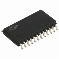
CY7C63613-SC Cypress Semiconductor Corp, CY7C63613-SC Datasheet - Page 23

CY7C63613-SC
Manufacturer Part Number
CY7C63613-SC
Description
IC MCU 8K USB LS MCU 24-SOIC
Manufacturer
Cypress Semiconductor Corp
Series
M8™r
Datasheet
1.CY7C63613-SC.pdf
(30 pages)
Specifications of CY7C63613-SC
Applications
USB Microcontroller
Core Processor
M8B
Program Memory Type
OTP (8 kB)
Controller Series
CY7C636xx
Ram Size
256 x 8
Interface
PS2, USB
Number Of I /o
16
Voltage - Supply
4 V ~ 5.5 V
Operating Temperature
0°C ~ 70°C
Mounting Type
Surface Mount
Package / Case
24-SOIC (7.5mm Width)
Lead Free Status / RoHS Status
Contains lead / RoHS non-compliant
Other names
428-1321
Available stocks
Company
Part Number
Manufacturer
Quantity
Price
Company:
Part Number:
CY7C63613-SC
Manufacturer:
CYP
Quantity:
5 510
Part Number:
CY7C63613-SC
Manufacturer:
CYPRESS/赛普拉斯
Quantity:
20 000
14.2.2
There are two timer interrupts: the 128- s interrupt and the 1.024-ms interrupt. The user should disable both timer interrupts
before going into the suspend mode to avoid possible conflicts between servicing the interrupts first or the suspend request first.
14.2.3
There are three USB endpoint interrupts, one per endpoint. The USB endpoints interrupt after the either the USB host or the USB
controller sends a packet to the USB.
14.2.4
Each DAC I/O pin can generate an interrupt, if enabled.The interrupt polarity for each DAC I/O pin is programmable. A positive
polarity is a rising edge input while a negative polarity is a falling edge input. All of the DAC pins share a single interrupt vector,
which means the firmware will need to read the DAC port to determine which pin or pins caused an interrupt.
Please note that if one DAC pin triggered an interrupt, no other DAC pins can cause a DAC interrupt until that pin has returned
to its inactive (non-trigger) state or the corresponding interrupt enable bit is cleared. The USB Controller does not assign interrupt
priority to different DAC pins and the DAC Interrupt Enable Register is not cleared during the interrupt acknowledge process.
14.2.5
Each of the 32 GPIO pins can generate an interrupt, if enabled. The interrupt polarity can be programmed for each GPIO port as
part of the GPIO configuration. All of the GPIO pins share a single interrupt vector, which means the firmware will need to read
the GPIO ports with enabled interrupts to determine which pin or pins caused an interrupt.
Please note that if one port pin triggered an interrupt, no other port pins can cause a GPIO interrupt until that port pin has returned
to its inactive (non-trigger) state or its corresponding port interrupt enable bit is cleared. The USB Controller does not assign
interrupt priority to different port pins and the Port Interrupt Enable Registers are not cleared during the interrupt acknowledge
process.
15.0
Table 15-1. USB Register Mode Encoding
Mode
Disable
Nak In/Out
Status Out Only
Stall In/Out
Ignore In/Out
Isochronous Out
Status In Only
Isochronous In
Nak Out
Ack Out
Nak Out - Status
In
Ack Out - Status
In
Nak In
Ack In
Nak In - Status
Out
Ack In - Status
Out
Timer Interrupt
USB Endpoint Interrupts
DAC Interrupt
GPIO Interrupt
Truth Tables
Encoding
0000
0001
0010
0011
0100
0101
0110
0111
1000
1001
1010
1011
1100
1101
1110
1111
accept
accept
accept
accept
accept
accept
accept
accept
accept
ignore
ignore
ignore
ignore
ignore
ignore
ignore
Setup
FOR
PRELIMINARY
ignore
ignore
ignore
TX cnt
TX cnt
TX cnt
ignore
ignore
NAK
TX 0
TX 0
TX 0
NAK
NAK
stall
stall
In
always
ignore
ignore
ignore
ignore
ignore
Check
check
check
NAK
NAK
ACK
NAK
ACK
stall
stall
Out
23
Comments
Ignore all USB traffic to this endpoint
Forced from Set-up on Control endpoint, from modes other
than 0000
For Control endpoints
For Control endpoints
For Control endpoints
Available to low speed devices, future USB spec
enhancements
For Control Endpoints
Available to low speed devices, future USB spec
enhancements
An ACK from mode 1001 --> 1000
This mode is changed by SIE on issuance of ACK --> 1000
An ACK from mode 1011 --> 1010
This mode is changed by SIE on issuance of ACK --> 1010
An ACK from mode 1101 --> 1100
This mode is changed by SIE on issuance of ACK --> 1100
An ACK from mode 1111 --> 111 Ack In - Status Out
This mode is changed by SIE on issuance of ACK -->1110
CY7C63612/13


