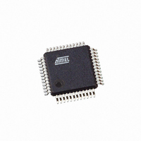
AT43USB326-AU Atmel, AT43USB326-AU Datasheet - Page 59

AT43USB326-AU
Manufacturer Part Number
AT43USB326-AU
Description
IC USB KEYBOARD CTRLR 48LQFP
Manufacturer
Atmel
Series
AVR®r
Datasheet
1.AT43USB326-AC.pdf
(102 pages)
Specifications of AT43USB326-AU
Applications
Keyboard Controller
Core Processor
AVR
Program Memory Type
Mask ROM (16 kB)
Controller Series
AT43USB
Ram Size
512 x 8
Interface
USB
Number Of I /o
32
Voltage - Supply
4.4 V ~ 5.25 V
Operating Temperature
-40°C ~ 85°C
Mounting Type
Surface Mount
Package / Case
48-LQFP
Lead Free Status / RoHS Status
Lead free / RoHS Compliant
Available stocks
Company
Part Number
Manufacturer
Quantity
Price
3313D–USB–04/06
Hub Endpoint 0 Control and Acknowledge Register – HCAR0
Function Endpoint 0 Control and Acknowledge Register – FCAR0
• Bit 7 – DIR: Control transfer direction
It is set by the microcontroller firmware to indicate the direction of a control transfer to the USB
hardware. The FW writes to this bit location after it receives an RX SETUP interrupt. The hard-
ware uses this bit to determine the status phase of a control transfer.
0 = control write or no data stage
1 = control read
• Bit 6 – DATA END
When set to 1 by firmware, this bit indicate that the microcontroller has either placed the last
data packet in FIFO, or that the microcontroller has processed the last data packet it expects
from the Host. This bit is used by control endpoints only together with bit 4 (TX Packet Ready)
to signal the USB hardware to go to the STATUS phase after the packet currently residing in
the FIFO is transmitted. After the hardware completes the STATUS phase it will interrupt the
microcontroller without clearing this bit.
• Bit 5 – FORCE STALL
This bit is set by the microcontroller to indicate a stalled endpoint. The hardware will send a
STALL handshake as a response to the next IN or OUT token, or whenever there is a control
transfer without a Data Stage.
The microcontroller sets this bit if it wants to force a STALL. A STALL is sent if any of the fol-
lowing condition is encountered:
1. An unsupported request is received.
2. The host continues to ask for data after the data is exhausted.
3. The control transfer has no data stage.
• Bit 4 – TX PACKET READY: Transmit Packet Ready
When set by the firmware, this bit indicates that the microcontroller has loaded the FIFO with a
packet of data. This bit is cleared by the hardware after the USB Host acknowledges the
packet. For ISO endpoints, this bit is cleared unconditionally after the data is sent.
This bit is used for the following operations:
1. Control read transactions by a control endpoint.
2. IN transactions with DATA1 PID to complete the status phase for a control endpoint,
3. By a BULK IN or ISO IN or INT IN endpoint.
The microcontroller should write into the FIFO only if this bit is cleared. After it has completed
writing the data, it should set this bit. This data can be of zero length.
Bit
Hub EP0
$1FA7
Function
EP0 $1FDD
Read/Write
Initial Value
when this bit is zero but Data End set high (bit 4).
R/W
DIR
DIR
7
0
DATA
DATA
R/W
END
END
6
0
FORCE
FORCE
STALL
STALL
R/W
5
0
PACKET
PACKET
READY
READY
R/W
TX
TX
4
0
STALL_
STALL_
SENT_
SENT_
R/W
ACK
ACK
3
0
SETUP_
SETUP_
R/W
ACK
ACK
RX_
RX_
2
0
RX_OUT_
RX_OUT_
PACKET_
PACKET_
R/W
ACK
ACK
AT43USB326
1
0
COMPLETE_
COMPLETE_
R/W
ACK
ACK
TX_
TX_
0
0
HCAR0
FCAR0
59


