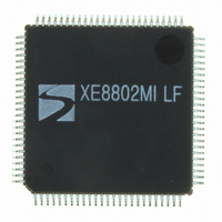
XE8802MI035LF Semtech, XE8802MI035LF Datasheet - Page 140

XE8802MI035LF
Manufacturer Part Number
XE8802MI035LF
Description
IC DAS 16BIT FLASH 8K 100-LQFP
Manufacturer
Semtech
Datasheet
1.XE8802MI035LF.pdf
(193 pages)
Specifications of XE8802MI035LF
Applications
Sensing Machine
Core Processor
RISC
Program Memory Type
FLASH (22 kB)
Controller Series
XE8000
Ram Size
1K x 8
Interface
SPI, UART
Number Of I /o
36
Voltage - Supply
2.4 V ~ 5.5 V
Operating Temperature
-40°C ~ 85°C
Mounting Type
Surface Mount
Package / Case
100-LQFP
For Use With
XE8000MP - PROG BOARD AND PROSTART2 CARD
Lead Free Status / RoHS Status
Lead free / RoHS Compliant
Available stocks
Company
Part Number
Manufacturer
Quantity
Price
Company:
Part Number:
XE8802MI035LF
Manufacturer:
TI
Quantity:
8 700
- Current page: 140 of 193
- Download datasheet (2Mb)
17.9 Application Hints
17.9.1
The PGAs of the acquisition chain employ switched-capacitor techniques. For this reason, while a conversion is
done, the input impedance on the selected channel of the PGAs is inversely proportional to the sampling frequency
f
The input impedance observed is the input impedance of the first PGA stage that is enabled or the input
impedance of the ADC if all three stages are disabled.
PGA1 (with a gain of 10), PGA2 (with a gain of 10) and PGA3 (with a gain of 10) each have a minimum input
impedance of 150kΩ at f
reducing the gain and/or by reducing the sampling frequency. Therefore, with a gain of 1 and a sampling frequency
of 100kHz, Z
The input impedance on channels that are not selected is very high (>100MΩ).
17.9.2
PGAs are reset after each writing operation to registers RegAcCfg1-5. Similarly, input channels are switched after
modifications of AMUX[4:0] or VMUX. To ensure precise conversion, the ADC must be started after a PGA or
inputs common-mode stabilization delay. This is done by writing bit START several cycles after modification of PGA
settings or channel switching. Delay between PGA start or input channel switching and ADC start should be
equivalent to OSR (between 8 and 1024) number of cycles. This delay does not apply to conversions made without
the PGAs.
If the ADC is not settled within the specified period, there is probably an input impedance problem (see previous
section).
17.9.3
Hereafter are a few design guidelines that should be taken into account when using the ZoomingADC™:
© Semtech 2006
S
and to stage gain as given in equation 22.
1)
2)
3)
4)
4)
5)
6)
Z
Keep in mind that increasing the overall PGA gain, or "zooming" coefficient, improves linearity but
degrades noise performance.
Use the minimum number of PGA stages necessary to produce the desired gain ("zooming") and offset.
Bypass unnecessary PGAs.
For high gains (>50), use PGA stage 1. For low gains (<50) use stages 2 and 3.
For the lowest noise, set the highest possible gain on the first (front) PGA stage used in the chain. For
example, in an application where a gain of 20 is needed, set the gain of PGA2 to 10, set the gain of PGA3
to 2.
For highest linearity and lowest noise performance, bypass all PGAs and use the ADC alone (applications
where no "zooming" is needed); i.e. set ENABLE[3:0] = '0001'.
For low-noise applications where power consumption is not a primary concern, maintain the largest bias
currents in the PGAs and in the ADC; i.e. set IB_AMP_PGA[1:0] = IB_AMP_ADC[1:0] = '11'.
For lowest output offset error at the output of the ADC, bypass PGA2 and PGA3. Indeed, PGA2 and
PGA3 typically introduce an offset of about 5 to 10 LSB (16 bit) at their output. Note, however, that the
ADC output offset is easily calibrated out by software.
in
Input Impedance
PGA Settling or Input Channel Modifications
PGA Gain & Offset, Linearity and Noise
≥
in
> 7.6MΩ.
768
f
s
⋅
10
⋅
gain
9
Ω
Hz
S
= 512kHz (see Specification Table). Larger input impedance can be obtained by
(Eq. 22)
XE8802 Sensing Machine Data Acquisition MCU
17-28
with ZoomingADC™ and LCD driver
www.semtech.com
Related parts for XE8802MI035LF
Image
Part Number
Description
Manufacturer
Datasheet
Request
R

Part Number:
Description:
EVALUATION BOARD
Manufacturer:
Semtech
Datasheet:

Part Number:
Description:
EVALUATION BOARD
Manufacturer:
Semtech
Datasheet:

Part Number:
Description:
VOLTAGE SUPPRESSOR, TRANSIENT SEMTECH
Manufacturer:
Semtech
Datasheet:

Part Number:
Description:
HIGH VOLTAGE CAPACITORS MONOLITHIC CERAMIC TYPE
Manufacturer:
Semtech Corporation
Datasheet:

Part Number:
Description:
EZ1084CM5.0 AMP POSITIVE VOLTAGE REGULATOR
Manufacturer:
Semtech Corporation
Datasheet:

Part Number:
Description:
3.0 AMP LOW DROPOUT POSITIVE VOLTAGE REGULATORS
Manufacturer:
Semtech Corporation
Datasheet:

Part Number:
Description:
Manufacturer:
Semtech Corporation
Datasheet:

Part Number:
Description:
RailClamp Low Capacitance TVS Diode Array
Manufacturer:
Semtech Corporation
Datasheet:

Part Number:
Description:
Manufacturer:
Semtech Corporation
Datasheet:

Part Number:
Description:
Manufacturer:
Semtech Corporation
Datasheet:

Part Number:
Description:
Manufacturer:
Semtech Corporation
Datasheet:

Part Number:
Description:
Manufacturer:
Semtech Corporation
Datasheet:


