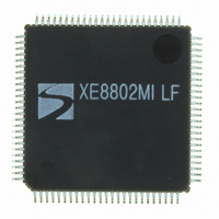
XE8802MI035LF Semtech, XE8802MI035LF Datasheet - Page 109

XE8802MI035LF
Manufacturer Part Number
XE8802MI035LF
Description
IC DAS 16BIT FLASH 8K 100-LQFP
Manufacturer
Semtech
Datasheet
1.XE8802MI035LF.pdf
(193 pages)
Specifications of XE8802MI035LF
Applications
Sensing Machine
Core Processor
RISC
Program Memory Type
FLASH (22 kB)
Controller Series
XE8000
Ram Size
1K x 8
Interface
SPI, UART
Number Of I /o
36
Voltage - Supply
2.4 V ~ 5.5 V
Operating Temperature
-40°C ~ 85°C
Mounting Type
Surface Mount
Package / Case
100-LQFP
For Use With
XE8000MP - PROG BOARD AND PROSTART2 CARD
Lead Free Status / RoHS Status
Lead free / RoHS Compliant
Available stocks
Company
Part Number
Manufacturer
Quantity
Price
Company:
Part Number:
XE8802MI035LF
Manufacturer:
TI
Quantity:
8 700
- Current page: 109 of 193
- Download datasheet (2Mb)
Note: for both cases, it is not required to toggle the NSS signal back to high and back to low between each byte
transmitted.
The SPI interface can be operated by polling the RegSpiStatus register or interrupt driven. The interrupt is active
on reception of a new byte.
In case of a multi-slave configuration, any digital output pin of any parallel port can be used to select the different
slaves. In some cases, it might be easier to have DC signals on these pins and to derive the timing from the single
NSS pin independently from the selected slave. This can be realized by combining the NSS wire from the master
device with signals coming from an output port as shown in Figure 16-4.
Pull-up resistors can be added on the input pads (MISO in master mode, MOSI, NSS and SCK in slave mode) by
setting the corresponding bits in RegSpiPullup. Use Table 16-2 for the correspondence between the pads and
register bits.
16.5.1.2 Master/Slave synchronization
In the master mode, a transmission is started by writing a 1 to the bit SpiTxEmpty. This automatically loads the
data of the register RegSpiDataOut to the shift register and starts the clock and shifting. At the end of the
transmission, the clock stops and the received data are copied to RegSpiDataIn. The bit SpiTxEmpty should not
be asserted while the previous transmission is still running, otherwise, the transmitted and received data will be
corrupted.
In slave mode, the fastest clock in the circuit should be at least 4 times faster than the baud rate of the
transmission. The transmission is synchronized by the NSS input signal. While the NSS signal is high, the counters
controlling the transmission are reset. The reception starts at the first clock cycle after the falling edge of NSS. At
the end of the transmission, the received data are copied to RegSpiDataIn and the contents of the register
RegSpiDataOut are copied automatically to the shift register. The data in the shift register can be overwritten by
writing 1 to SpiTxEmpty. This should not be done while a transmission is running, otherwise, the transmitted and
received data will be corrupted.
The counters controlling the timing of the transmission can be reset by writing a 1 to the ClearCounters bit in the
RegSpiControl register. In master mode, it restarts a complete transmission cycle. In slave mode, it has the same
effect as a rising edge of NSS. This bit should be used with caution.
© Semtech 2006
SCK cycle
SCK
(CPOL=0)
SCK
(CPOL=1)
MOSI
MISO
NSS
MSB
MSB
1
Figure 16-3: SPI transmission format with ClockPhase=1
bit 6
bit 6
2
bit 5
bit 5
3
XE8802 Sensing Machine Data Acquisition MCU
bit 4
bit 4
4
16-6
bit 3
bit 3
5
with ZoomingADC™ and LCD driver
bit 2
bit 2
6
bit 1
bit 1
7
LSB
LSB
8
www.semtech.com
Related parts for XE8802MI035LF
Image
Part Number
Description
Manufacturer
Datasheet
Request
R

Part Number:
Description:
EVALUATION BOARD
Manufacturer:
Semtech
Datasheet:

Part Number:
Description:
EVALUATION BOARD
Manufacturer:
Semtech
Datasheet:

Part Number:
Description:
VOLTAGE SUPPRESSOR, TRANSIENT SEMTECH
Manufacturer:
Semtech
Datasheet:

Part Number:
Description:
HIGH VOLTAGE CAPACITORS MONOLITHIC CERAMIC TYPE
Manufacturer:
Semtech Corporation
Datasheet:

Part Number:
Description:
EZ1084CM5.0 AMP POSITIVE VOLTAGE REGULATOR
Manufacturer:
Semtech Corporation
Datasheet:

Part Number:
Description:
3.0 AMP LOW DROPOUT POSITIVE VOLTAGE REGULATORS
Manufacturer:
Semtech Corporation
Datasheet:

Part Number:
Description:
Manufacturer:
Semtech Corporation
Datasheet:

Part Number:
Description:
RailClamp Low Capacitance TVS Diode Array
Manufacturer:
Semtech Corporation
Datasheet:

Part Number:
Description:
Manufacturer:
Semtech Corporation
Datasheet:

Part Number:
Description:
Manufacturer:
Semtech Corporation
Datasheet:

Part Number:
Description:
Manufacturer:
Semtech Corporation
Datasheet:

Part Number:
Description:
Manufacturer:
Semtech Corporation
Datasheet:


