20-101-0672 Rabbit Semiconductor, 20-101-0672 Datasheet - Page 21
20-101-0672
Manufacturer Part Number
20-101-0672
Description
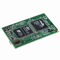
MODULE RABBITCORE RCM3600
Manufacturer
Rabbit Semiconductor
Datasheet
1.20-101-0673.pdf
(136 pages)
Specifications of 20-101-0672
Module/board Type
MPU Core Module
Product
Microcontroller Modules
Core Processor
Rabbit 3000
Clock Speed
22.1 MHz
Interface Type
Serial
Flash
512 KB
Timers
10 x 8 bit, 1 x 10 bit
Operating Supply Voltage
3 V to 3.6 V
Board Size
31 mm x 54 mm x 16 mm
Core
RCM3600
Processor Series
RCM3600
For Use With/related Products
RCM3600
Lead Free Status / RoHS Status
Lead free / RoHS Compliant
Other names
316-1102


•
•
•
Once you have loaded and executed these five programs and have an understanding of
how Dynamic C and the RCM3600 modules interact, you can move on and try the other
sample programs, or begin developing your own.
Getting Started
IR_DEMO.c
Board assemblies via the IrDA transceivers with the IrDA transceivers facing each other.
Note that this sample program requires a second Prototyping Board or Rabbit Semicon-
ductor single-board computer that has an IrDA chip and is running the
sample program associated with it.
First, compile and run the
cific to the other system on the second system, then remove the programming cable and
press the
connect the programming cable to the RCM3600 module, and compile and run the
IR_DEMO.C
system. With the two IrDA transceivers facing each other, press switch S1 on the
RCM3600 Prototyping Board to transmit a packet. The other system will return a
response packet that will then appear in the Dynamic C
ets and response packets have different codes.
DIO.c
typing Board by configuring two lines to outputs and two lines as inputs on Prototyping
Board header JP4.
Install a 2 × 2 header at JP4 on the Prototyping Board and connect pins 1–3 and pins 2–4
on header JP4 before running this sample program.
Once the sample program is compiled and running, it will prompt you in the
window to select either pin 1 of header JP4 or pin 2 of header JP4 for the output. Once
you have made that selection, you will be prompted to enter a logic 0 or 1. The speci-
fied logic level will then be output on pins 1–3 or pins 2–4 on header JP4.
TOGGLESWITCH.c
responding LEDs (DS1 and DS2) will turn on or off. LEDs DS1 and DS2 on the Proto-
typing Board are turned on and off when you press switches S1 and S2. S1 and S2 are
controlled by PF4 and PB7 respectively.
—Demonstrates the digital I/O capabilities of the A/D converter on the Proto-
RESET
—Demonstrates sending Modbus ASCII packets between two Prototyping
sample program from the
button so that the first assembly is operating in the
—Uses costatements to detect switches using debouncing. The cor-
IR_DEMO.C
SAMPLES\RCM3600
sample program from the
STDIO
folder on the RCM3600
window. The test pack-
SAMPLES
Run
IR_DEMO.C
mode. Then
folder spe-
STDIO
15
Related parts for 20-101-0672
Image
Part Number
Description
Manufacturer
Datasheet
Request
R

Part Number:
Description:
COMPUTER SGL-BRD BL2500 29.4MHZ
Manufacturer:
Rabbit Semiconductor
Datasheet:

Part Number:
Description:
COMPUTER SGL-BRD BL2500 29.4MHZ
Manufacturer:
Rabbit Semiconductor
Datasheet:

Part Number:
Description:
DISPLAY GRAPHIC 12KEY PROG OP670
Manufacturer:
Rabbit Semiconductor
Datasheet:
Part Number:
Description:
DISPLAY GRAPHIC 12KEY ETH OP6700
Manufacturer:
Rabbit Semiconductor
Datasheet:

Part Number:
Description:
COMPUTER SINGLE-BOARD BL2030
Manufacturer:
Rabbit Semiconductor
Part Number:
Description:
COMPUTER SGL-BOARD ETH BL2010
Manufacturer:
Rabbit Semiconductor

Part Number:
Description:
MODULE OP6810 W/O ETH/MEM EXPANS
Manufacturer:
Rabbit Semiconductor
Datasheet:
Part Number:
Description:
COMPUTER SINGLE-BOARD BL2020
Manufacturer:
Rabbit Semiconductor
Part Number:
Description:
COMPUTER BL2010 W/FRICTION LOCK
Manufacturer:
Rabbit Semiconductor
Part Number:
Description:
COMPUTER BL2020 W/FRICTION LOCK
Manufacturer:
Rabbit Semiconductor
Part Number:
Description:
COMPUTER SGL-BRD BL2500 44.2MHZ
Manufacturer:
Rabbit Semiconductor
Datasheet:
Part Number:
Description:
COMPUTER SGL-BOARD FULL BL2000
Manufacturer:
Rabbit Semiconductor

Part Number:
Description:
COMPUTER SINGLE-BOARD BL2110
Manufacturer:
Rabbit Semiconductor

Part Number:
Description:
COMPUTER SGL-BRD 29.4MHZ BL2610
Manufacturer:
Rabbit Semiconductor
Datasheet:
Part Number:
Description:
INTERFACE OP6800 512K FLASH&SRAM
Manufacturer:
Rabbit Semiconductor
Datasheet: