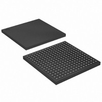
XC2S150E-6FT256I Xilinx Inc, XC2S150E-6FT256I Datasheet - Page 10

XC2S150E-6FT256I
Manufacturer Part Number
XC2S150E-6FT256I
Description
SPARTAN FPGA 150000 GATE 1.8V
Manufacturer
Xilinx Inc
Series
Spartan™-IIEr
Datasheet
1.XC2S50E-6TQG144C.pdf
(108 pages)
Specifications of XC2S150E-6FT256I
Number Of Logic Elements/cells
3888
Number Of Labs/clbs
864
Total Ram Bits
49152
Number Of I /o
182
Number Of Gates
150000
Voltage - Supply
1.71 V ~ 1.89 V
Mounting Type
Surface Mount
Operating Temperature
-40°C ~ 100°C
Package / Case
256-LBGA
Lead Free Status / RoHS Status
Contains lead / RoHS non-compliant
Other names
Q1280323
Available stocks
Company
Part Number
Manufacturer
Quantity
Price
Spartan-IIE FPGA Family: Functional Description
Table 3: Standards Supported by I/O (Typical Values)
10
LVTTL (2-24 mA)
LVCMOS2
LVCMOS18
PCI (3V,
33 MHz/66 MHz)
GTL
GTL+
HSTL Class I
HSTL Class III
HSTL Class IV
SSTL3 Class I
and II
SSTL2 Class I
and II
CTT
AGP
LVDS, Bus LVDS
LVPECL
I/O Standard
Reference
Voltage
(V
Input
0.75
1.25
1.32
N/A
N/A
N/A
N/A
N/A
N/A
0.8
1.0
0.9
0.9
1.5
1.5
TFF
OFF
IFF
REF
)
Voltage
(V
Input
N/A
N/A
N/A
N/A
N/A
N/A
N/A
N/A
N/A
N/A
N/A
3.3
2.5
1.8
3.3
CCO
)
Figure 4: Spartan-IIE Input/Output Block (IOB)
Voltage
Source
Output
(V
N/A
N/A
3.3
2.5
1.8
3.3
1.5
1.5
1.5
3.3
2.5
3.3
3.3
2.5
3.3
CCO
)
Termination
Voltage
Board
(V
0.75
1.25
N/A
N/A
N/A
N/A
N/A
N/A
N/A
1.2
1.5
1.5
1.5
1.5
1.5
TT
)
www.xilinx.com
Input/Output Block
The Spartan-IIE FPGA IOB, as seen in
inputs and outputs that support a wide variety of I/O signal-
ing standards. These high-speed inputs and outputs are
capable of supporting various state of the art memory and
bus interfaces. The default standard is LVTTL.
several of the standards which are supported along with the
required reference (V
nation (V
more details on the I/O standards and termination applica-
tion examples, see XAPP179, "Using SelectIO Interfaces in
Spartan-II and Spartan-IIE FPGAs."
The three IOB registers function either as edge-triggered
D-type flip-flops or as level-sensitive latches. Each IOB has
a clock signal (CLK) shared by the three registers and inde-
pendent Clock Enable (CE) signals for each register.
In addition to the CLK and CE control signals, the three reg-
isters share a Set/Reset (SR). For each register, this signal
can be independently configured as a synchronous Set, a
synchronous Reset, an asynchronous Preset, or an asyn-
chronous Clear.
A feature not shown in the block diagram, but controlled by
the software, is polarity control. The input and output buffers
and all of the IOB control signals have independent polarity
controls.
TT
) voltages needed to meet the standard. For
REF
), output (V
DS077-2 (v2.3) June 18, 2008
CCO
Product Specification
) and board termi-
Figure
Table 3
4, features
lists
R


