VSMD1505-10K/10K-0.01-0.005 Vishay, VSMD1505-10K/10K-0.01-0.005 Datasheet - Page 2
VSMD1505-10K/10K-0.01-0.005
Manufacturer Part Number
VSMD1505-10K/10K-0.01-0.005
Description
Resistor Networks & Arrays 10K/10K 0.01-0.005 1505pkg TCR of 2ppm
Manufacturer
Vishay
Series
VSMD1505r
Datasheet
1.VSMD1505-10K10K-0.01-0.005.pdf
(4 pages)
Specifications of VSMD1505-10K/10K-0.01-0.005
Circuit Type
Dual Terminator
Number Of Resistors
2
Resistance
10 KOhms, 10 KOhms
Tolerance
0.01 %
Power Rating
400 mWatts
Temperature Coefficient
+/- 2 PPM / C
Package / Case
1505
Dimensions
0.46 mm Dia. x 1.27 mm W x 3.81 mm L x 0.64 mm H
Termination Style
SMD/SMT
Lead Free Status / Rohs Status
Lead free / RoHS Compliant


Note
1. Land Pattern Dimensions are per IPC-7351A
Note
1. As shown + 0.01 Ω to allow for measurement errors at low values.
Document Number: 63070
Revision: 18-Sep-08
Interloop Capacitance
Reduction in Series
FIGURE 2 - TRIMMING TO VALUES
TABLE 2 - DIMENSIONS AND LAND PATTERN in inches (millimeters)
CHIP SIZE
0805
1206
1506
2010
2512
TABLE 3 - SPECIFICATIONS
CHIP SIZE
0805
1206
1506
2010
2512
TABLE 4 - PERFORMANCES
TEST OR CONDITIONS
Thermal Shock
Low Temperature Operation
Short Time Overload
High Temperature Exposure
Resistance to Soldering Heat
Moisture Resistance
Load Life Stability + 70 °C for 2000 h at Rated Power
Mutual Inductance
Reduction due
to Change in
Current Direction
± 0.005 (0.13)
0.080 (2.03)
0.126 (3.20)
0.150 (3.81)
0.198 (5.03)
0.249 (6.32)
(Conceptual Illustration)
T
Note: Foil shown in black, etched spaces in white
L
RATED POWER (mW)
± 0.005 (0.13)
and Load Life Stability of ± 0.01 % (100 ppm)
Top View
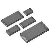
Mount Chip Resistor with TCR of ± 2 ppm/°C
0.050 (1.27)
0.062 (1.57)
0.062 (1.57)
0.097 (2.46)
0.127 (3.23)
at + 70 °C
High Precision Foil Wraparound Surface
D
100
150
200
300
400
W
After Trimming
Current Path
L
from Shorting Strip Area
Changing Current Path
Removes this Material
Trimming Process
and Increasing
Resistance
Before Trimming
VSM Series (0805, 1206, 1506, 2010, 2512)
THICKNESS
For any questions, contact: foil@vishay.com
Current Path
0.025 (0.64)
0.025 (0.64)
0.025 (0.64)
0.025 (0.64)
0.025 (0.64)
W
MAXIMUM
MAX VOLTAGE RATING
CHARACTERISTIC E
MIL-PRF-55342
(≤
ΔR LIMITS
± 0.1 %
± 0.1 %
± 0.1 %
± 0.1 %
± 0.2 %
± 0.2 %
± 0.5 %
173 V
220 V
34 V
67 V
89 V
P R
± 0.005 (0.13)
×
0.015 (0.38)
0.020 (0.51)
0.020 (0.51)
0.025 (0.64)
0.032 (0.81)
Note
• The TCR values for < 100 Ω are influenced by the termination
)
FIGURE 3 -TYPICAL TCR CURVE
composition and result in deviation from this curve.
D
(ppm)
∆
R
Recommended Land Pattern
R
+ 150
+ 100
- 100
- 150
- 200
Z
+ 50
- 50
0
- 55
G
RESISTANCE RANGE
- 50
± 0.005 % (50 ppm)
± 0.01 % (100 ppm)
± 0.01 % (100 ppm)
± 0.01 % (100 ppm)
± 0.005 % (50 ppm)
± 0.005 % (50 ppm)
± 0.005 % (50 ppm)
0.122 (3.10)
0.175 (4.45)
0.199 (5.05)
0.247 (6.27)
0.291 (7.39)
MAXIMUM
(For more details, see Table 1)
ΔR LIMITS
10 to 100K
10 to 150K
TYPICAL
- 25
10 to 12K
10 to 30K
10 to 40K
Z
1)
(Ω)
Ambient Temperature (°C)
0
Vishay Foil Resistors
X
+ 25
0.028 (0.71)
0.059 (1.50)
0.083 (2.11)
0.115 (2.92)
0.150 (3.81)
MINIMUM
Footprint
G
+ 50
1)
± 2 ppm/°C
(+ 25 °C reference)
MAXIMUM WEIGHT
± 0.02 % (200 ppm)
± 0.02 % (200 ppm)
± 0.02 % (200 ppm)
± 0.03 % (300 ppm)
± 0.01 % (100 ppm)
± 0.03 % (300 ppm)
± 0.01 % (100 ppm)
+ 75
ΔR LIMITS
MAXIMUM
(mg)
www.vishay.com
0.050 (1.27)
0.071 (1.80)
0.071 (1.80)
0.103 (2.62)
0.127 (3.23)
11
12
27
40
+ 100
6
MAXIMUM
X
1)
1)
+ 125
2
Related parts for VSMD1505-10K/10K-0.01-0.005
Image
Part Number
Description
Manufacturer
Datasheet
Request
R

Part Number:
Description:
357-036-542-201 CARDEDGE 36POS DL .156 BLK LOPRO
Manufacturer:
Vishay
Datasheet:
Part Number:
Description:
357-036-542-201 CARDEDGE 36POS DL .156 BLK LOPRO
Manufacturer:
Vishay
Datasheet:
Part Number:
Description:
357-036-542-201 CARDEDGE 36POS DL .156 BLK LOPRO
Manufacturer:
Vishay
Datasheet:
Part Number:
Description:
357-036-542-201 CARDEDGE 36POS DL .156 BLK LOPRO
Manufacturer:
Vishay
Datasheet:
Part Number:
Description:
357-036-542-201 CARDEDGE 36POS DL .156 BLK LOPRO
Manufacturer:
Vishay
Datasheet:
Part Number:
Description:
357-036-542-201 CARDEDGE 36POS DL .156 BLK LOPRO
Manufacturer:
Vishay
Datasheet:
Part Number:
Description:
357-036-542-201 CARDEDGE 36POS DL .156 BLK LOPRO
Manufacturer:
Vishay
Datasheet:
Part Number:
Description:
357-036-542-201 CARDEDGE 36POS DL .156 BLK LOPRO
Manufacturer:
Vishay
Datasheet:
Part Number:
Description:
357-036-542-201 CARDEDGE 36POS DL .156 BLK LOPRO
Manufacturer:
Vishay
Datasheet:
Part Number:
Description:
357-036-542-201 CARDEDGE 36POS DL .156 BLK LOPRO
Manufacturer:
Vishay
Datasheet:
Part Number:
Description:
357-036-542-201 CARDEDGE 36POS DL .156 BLK LOPRO
Manufacturer:
Vishay
Datasheet:
Part Number:
Description:
357-036-542-201 CARDEDGE 36POS DL .156 BLK LOPRO
Manufacturer:
Vishay
Datasheet:
Part Number:
Description:
357-036-542-201 CARDEDGE 36POS DL .156 BLK LOPRO
Manufacturer:
Vishay
Datasheet:
Part Number:
Description:
357-036-542-201 CARDEDGE 36POS DL .156 BLK LOPRO
Manufacturer:
Vishay
Datasheet:
Part Number:
Description:
357-036-542-201 CARDEDGE 36POS DL .156 BLK LOPRO
Manufacturer:
Vishay
Datasheet: