VSMD1505-10K/10K-0.01-0.005 Vishay, VSMD1505-10K/10K-0.01-0.005 Datasheet - Page 3
VSMD1505-10K/10K-0.01-0.005
Manufacturer Part Number
VSMD1505-10K/10K-0.01-0.005
Description
Resistor Networks & Arrays 10K/10K 0.01-0.005 1505pkg TCR of 2ppm
Manufacturer
Vishay
Series
VSMD1505r
Datasheet
1.VSMD1505-10K10K-0.01-0.005.pdf
(4 pages)
Specifications of VSMD1505-10K/10K-0.01-0.005
Circuit Type
Dual Terminator
Number Of Resistors
2
Resistance
10 KOhms, 10 KOhms
Tolerance
0.01 %
Power Rating
400 mWatts
Temperature Coefficient
+/- 2 PPM / C
Package / Case
1505
Dimensions
0.46 mm Dia. x 1.27 mm W x 3.81 mm L x 0.64 mm H
Termination Style
SMD/SMT
Lead Free Status / Rohs Status
Lead free / RoHS Compliant


www.vishay.com
3
VSM Series (0805, 1206, 1506, 2010, 2512)
Vishay Foil Resistors
Notes
1. Avoid the use of cleaning agents which could attack epoxy resins,
2. Vacuum pick up is recommended for handling
3. Soldering iron may damage the resistor
Note
* For non-standard requests, please contact application engineering.
FIGURE 4 - RECOMMENDED
TABLE 6 - GLOBAL PART NUMBER INFORMATION
NEW GLOBAL PART NUMBER: Y145512K7560T9R (preferred part number format)
FOR EXAMPLE: ABOVE GLOBAL ORDER Y1455 12K7565 T 9 R:
TYPE: VSM1506
VALUES: 12.7560 kΩ
ABSOLUTE TOLERANCE: 0.01 %
TERMINATION: lead (Pb)-free
PACKAGING: tape and reel
HISTORICAL PART NUMBER: VSM1506 12K756 TCR2 T S T (will continue to be used)
which form part of the resistor construction
VSM1506
VSM0805
VSM1206
VSM1506
VSM2010
VSM2512
MODEL
Y
DENOTES PRECISION
PRODUCT CODE
1172 = VSM0805
1496 = VSM1206
1455 = VSM1506
1611 = VSM2010
1612 = VSM2512
MOUNTING
1
Y
RESISTANCE VALUE
25 % to 85 % of T
4
12.756 kΩ
12K756
A low profile solder fillet is
recommended to avoid unnecessary
stresses along top edge of
metallization. IR and vapor phase
reflow are best.
5
1)2)3)
and Load Life Stability of ± 0.01 % (100 ppm)
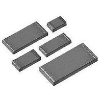
Mount Chip Resistor with TCR of ± 2 ppm/°C
High Precision Foil Wraparound Surface
5
For any questions, contact: foil@vishay.com
CHARACTERISTICS
1
TCR2
TCR
RESISTANCE TOLERANCE
2
T = ± 0.01 %
Q = ± 0.02 %
A = ± 0.05 %
B = ± 0.10 %
C = ± 0.25 %
D = ± 0.5 %
F = ± 1.0 %
VALUE
R = Ω
K = kΩ
K
TOLERANCE
T = ± 0.01 %
Q = ± 0.02 %
A = ± 0.05 %
B = ± 0.10 %
C = ± 0.25 %
D = ± 0.5 %
F = ± 1.0 %
TABLE 5 - SPACE AND MILITARY
VSM0805
VSM1206
VSM1506
VSM2010
VSM2512
7
MODEL
T
5
EEE-INST-002
SPECIFICATIONS
6
S = lead (Pb)-free
B = tin/lead
TERMINATION
√
√
√
√
√
0
S
0 = standard
9 = lead (Pb)-free
1 - 999 = custom
R = tape and reel
W = waffle pack
PACKAGING
T
DSCC
07024
07025
03010
06001
06002
AER*
Document Number: 63070
T = tape and reel
W = waffle pack
9
Revision: 18-Sep-08
PACKAGING
MIL-PRF
T
R
55342
Related parts for VSMD1505-10K/10K-0.01-0.005
Image
Part Number
Description
Manufacturer
Datasheet
Request
R

Part Number:
Description:
357-036-542-201 CARDEDGE 36POS DL .156 BLK LOPRO
Manufacturer:
Vishay
Datasheet:
Part Number:
Description:
357-036-542-201 CARDEDGE 36POS DL .156 BLK LOPRO
Manufacturer:
Vishay
Datasheet:
Part Number:
Description:
357-036-542-201 CARDEDGE 36POS DL .156 BLK LOPRO
Manufacturer:
Vishay
Datasheet:
Part Number:
Description:
357-036-542-201 CARDEDGE 36POS DL .156 BLK LOPRO
Manufacturer:
Vishay
Datasheet:
Part Number:
Description:
357-036-542-201 CARDEDGE 36POS DL .156 BLK LOPRO
Manufacturer:
Vishay
Datasheet:
Part Number:
Description:
357-036-542-201 CARDEDGE 36POS DL .156 BLK LOPRO
Manufacturer:
Vishay
Datasheet:
Part Number:
Description:
357-036-542-201 CARDEDGE 36POS DL .156 BLK LOPRO
Manufacturer:
Vishay
Datasheet:
Part Number:
Description:
357-036-542-201 CARDEDGE 36POS DL .156 BLK LOPRO
Manufacturer:
Vishay
Datasheet:
Part Number:
Description:
357-036-542-201 CARDEDGE 36POS DL .156 BLK LOPRO
Manufacturer:
Vishay
Datasheet:
Part Number:
Description:
357-036-542-201 CARDEDGE 36POS DL .156 BLK LOPRO
Manufacturer:
Vishay
Datasheet:
Part Number:
Description:
357-036-542-201 CARDEDGE 36POS DL .156 BLK LOPRO
Manufacturer:
Vishay
Datasheet:
Part Number:
Description:
357-036-542-201 CARDEDGE 36POS DL .156 BLK LOPRO
Manufacturer:
Vishay
Datasheet:
Part Number:
Description:
357-036-542-201 CARDEDGE 36POS DL .156 BLK LOPRO
Manufacturer:
Vishay
Datasheet:
Part Number:
Description:
357-036-542-201 CARDEDGE 36POS DL .156 BLK LOPRO
Manufacturer:
Vishay
Datasheet:
Part Number:
Description:
357-036-542-201 CARDEDGE 36POS DL .156 BLK LOPRO
Manufacturer:
Vishay
Datasheet: