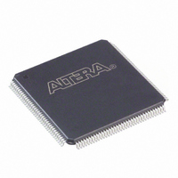
EPM570T144I5N Altera, EPM570T144I5N Datasheet - Page 41

EPM570T144I5N
Manufacturer Part Number
EPM570T144I5N
Description
IC MAX II CPLD 570 LE 144-TQFP
Manufacturer
Altera
Series
MAX® IIr
Specifications of EPM570T144I5N
Programmable Type
In System Programmable
Delay Time Tpd(1) Max
5.4ns
Voltage Supply - Internal
2.5V, 3.3V
Number Of Logic Elements/blocks
570
Number Of Macrocells
440
Number Of I /o
116
Operating Temperature
-40°C ~ 100°C
Mounting Type
Surface Mount
Package / Case
144-TQFP, 144-VQFP
Voltage
2.5V, 3.3V
Memory Type
FLASH
Number Of Logic Elements/cells
570
Lead Free Status / RoHS Status
Lead free / RoHS Compliant
Features
-
Other names
544-2283
Available stocks
Company
Part Number
Manufacturer
Quantity
Price
Company:
Part Number:
EPM570T144I5N
Manufacturer:
ALTERA52
Quantity:
980
Part Number:
EPM570T144I5N
Manufacturer:
ALTERA/阿尔特拉
Quantity:
20 000
Chapter 2: MAX II Architecture
Document Revision History
Document Revision History
Table 2–8. Document Revision History
© October 2008 Altera Corporation
Date and Revision
October 2008,
version 2.2
March 2008,
version 2.1
December 2007,
version 2.0
December 2006,
version 1.7
August 2006,
version 1.6
July 2006,
vervion 1.5
February 2006,
version 1.4
August 2005,
version 1.3
December 2004,
version 1.2
June 2004,
version 1.1
Changes Made
■
■
■
■
■
■
■
■
■
■
■
■
■
■
■
■
■
■
■
Table 2–8
Updated
Updated
Updated New Document Format.
Updated “Schmitt Trigger” section.
Updated “Clear and Preset Logic Control” section.
Updated “MultiVolt Core” section.
Updated “MultiVolt I/O Interface” section.
Updated Table 2–7.
Added “Referenced Documents” section.
Minor update in “Internal Oscillator” section. Added document
revision history.
Updated functional description and I/O structure sections.
Minor content and table updates.
Updated “LAB Control Signals” section.
Updated “Clear and Preset Logic Control” section.
Updated “Internal Oscillator” section.
Updated Table 2–5.
Removed Note 2 from Table 2-7.
Added a paragraph to page 2-15.
Added CFM acronym. Corrected Figure 2-19.
Table 2–4
“I/O Standards and Banks”
shows the revision history for this chapter.
and
Table
2–6.
section.
Summary of Changes
Updated document with
MAX IIZ information.
MAX II Device Handbook
—
—
—
—
—
—
—
—
—
2–33


