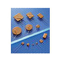
A91311-000 TE Connectivity, A91311-000 Datasheet - Page 25

A91311-000
Manufacturer Part Number
A91311-000
Description
Manufacturer
TE Connectivity
Datasheet
1.A91311-000.pdf
(27 pages)
Specifications of A91311-000
Hold Current
2.5A
Trip Current
5A
Initial Resistance (min)
20mOhm
Initial Resistance (max)
40mOhm
Voltage Rating Max
30V
Trip Time (max)
10.3@12.5As
Power Dissipation (typ)
1.2W
Post Trip Resistance (max)
70mOhm
Agency Approvals
CSA/TUV/UL
Operating Temperature Min Deg. C
-40C
Operating Temperature Max Deg. C
85C
Lead Free Status / Rohs Status
Compliant
Table R7 - Tape and Reel Specifications for Radial-leaded Devices
RGEF and RHEF devices are available in tape and reel packaging per EIA468–B/IEC60286–2 standards. See Figures R24 and R25 for details.
Dimension
Description
Carrier tape width
Hold-down tape width
Top distance between tape edges
Sprocket hole position
Sprocket hole diameter
Abscissa to plane (straight lead) RGEF250 to RGEF1400
Abscissa to plane (kinked lead) RHEF050 to RHEF1500
Abscissa to top RGEF250 to RGE6F00, RHEF050 to RHEF450
Abscissa to top* RGEF700 to RGEF1400, RHEF600 to RHEF1500
Overall width w/lead protrusion RGEF250 to RGEF600, RHEF050 to RHEF450
Overall width w/lead protrusion RGEF700 to RGEF1400, RHEF600 to RHEF1500
Overall width w/o lead protrusion RGEF250 to RGEF600, RHEF050 to RHEF450
Overall width w/o lead protrusion RGEF700 to RGEF1400, RHEF600 to RHEF1500
Lead protrusion
Protrusion of cut-out
Protrusion beyond hold-down tape
Sprocket hole pitch
Device pitch RGEF250 to RGEF700, RHEF050 to RHEF600
Device pitch RGEF800 to RGEF1400, RHEF650 to RHEF1500
Pitch tolerance
Tape thickness
Overall tape and lead thickness* RGEF250 to RGEF1100, RHEF050 to RHEF1000
Overall tape and lead thickness* RGEF1200 to RGEF1400, RHEF1300, RHEF1500
Splice sprocket hole alignment
Body lateral deviation
Body tape plane deviation
Ordinate to adjacent component lead RGEF300 to RGEF1100, RHEF400 to RHEF750
Ordinate to adjacent component lead RGEF1200 to RGEF1400, RHEF1000 to RHEF1500
Lead spacing* RGEF250 to RGEF1100, RHEF050 to RHEF900
Lead spacing* RGEF1200 to RGEF1400, RHEF1000 to RHEF1500
Reel width RGEF250 to RGEF600, RHEF050 to RHEF450
Reel width* RGEF600 to RGEF1400 & RHEF600 to RHEF1500
Reel diameter
Space between flanges less device*
Arbor hold diameter
Core diameter*
Box
Consecutive missing places
Empty places per reel
*Differs from EIA specification.
Figure R24 - EIA Referenced Taped Component Dimensions for Radial-leaded Devices
Δ h
H
Δ h
1
I
2
L
L
1
P
P
0
1
A
B
Reference plane
F
D
Mark
0
W
EIA
W
W
W
Δ
D
H
H
H
—
—
—
—
w
w
w
—
—
—
W
C
C
C
C
L
P
P
P
H
I
t
t
L
F
F
a
c
n
t
2
1
1
4
1
0
0
1
1
1
1
2
2
0
p
1
1
2
2
1
4
6
5
h
H
0
W
5
W
Direction of unreeling
Dimension (mm)
Cross section A - B
20 consecutive
Not specified
64/372/362
0.1%
370.0
16.0
10.2
63.5
26.0
91.0
None
18.5
32.2
45.0
43.2
42.5
12.7
25.4
25.4
3.81
7.62
5.08
56.0
4.75
1.0
0.9
2.0
2.3
18
11
55
54
11
3
9
4
0
0
0
H
H
1
C
1
C
t
2
Δ p
Tolerance
-0.5/+1.0
Minimum
Maximum
-0.5/+0.75
± 0.2
± 2.5
± 0.5
Maximum
Maximum
Maximum
Maximum
Maximum
Maximum
Maximum
Maximum
—
± 0.3
± 0.61
± 0.6
± 1
Maximum
Maximum
Maximum
± 0.3
± 1.0
± 1.3
± 0.7
± 0.7
+0.75 /-0.5
+ 0.75/-0.5
Maximum
Maximum
Maximum
± 3.25
± 12.0
Maximum
Maximum
—
Maximum
Δ p
...
Cont'd
1 34
13


